To have the recorder display a camera when the vehicle is put into reverse, follow the steps below
Step 1 - Configuring a Tour
Grey Interface
- Go to Main Menu > Setting > System > Display.
- Now click the Tour Setup button to enter the Tour menu.

- Remove all entries by changing the window split then deleting the channel group.
- Select Window Split as View 1 then select the reverse camera.
- The tour is now configured.
Black GUI
 |
|
 |
Select the number of views you want the tour to see |
 |
Add / Modify the group of cameras for the tour |
Step 2 - Configuring the Alarm Input
Grey GUI
1. Go to the Main Menu > Setting > Event > Alarm

2. Enable the alarm input, then select the type, N.O or N.C
3. Enable the tour button and select the tour preset which contains the reversing camera in full screen.
DeleteStep 3 - Enable Alarm Recording Schedule
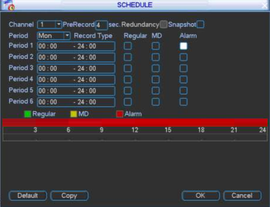
- Go to Main Menu > System > Schedule.
-
Enable Alarm for your chose period to record alarm events.

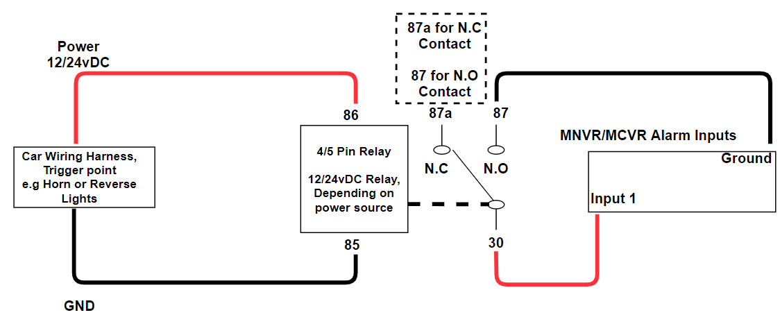
Wiring Diagram - Triggering an Alarm Input via External Relay

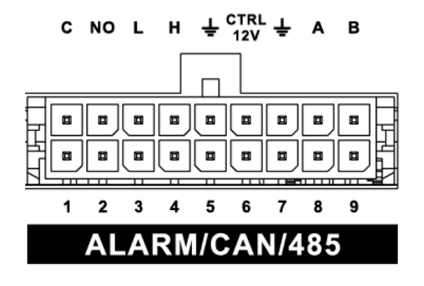
Alarm Inputs/Output Diagram

| Name | Pin Definition |
|
1~9 NO or NC |
Input 1-7 - Normal Input Input 8-9 - Pulse Input |
| C, NO | C - Common NO - Normally Open The alarm output maximum load is 0.5A. Use an external relay for higher current devices. |
| L, H | CAN Port |
 |
Alarm Ground |
| A, B | RS485 Port |

