Table of Contents
Presets, Tours, Scans, Patterns and PansIdle Motion, PowerUp and Time TaskMotion Detection & Smart Motion DetectionIVS & Face Detection/RecognitionAuto TrackingAdditional ConfigurationPlease note, that not all VIP Vision cameras support all of the functions listed below. To check what functions a particular model camera has, please refer to the camera datasheet.
Presets, Tours, Scans, Patterns and Pans
There are multiple options for configuring how the PTZ will function. See below for the different types and how to configure them.
Preset - A saved position. The cameras Pan (Left/Right), Tilt (Up/Down), Zoom (In/Out) and focus position is saved in the preset.
Tour - A collection of presets that the PTZ moves between automatically.
Scan - The PTZ will move left and right between set boundaries at a set speed.
Pattern - A recorded series of pan, tilt and zoom movements that will be performed on repeat.
Pan - The PTZ will spin 360° at a set speed.
Presets
A Preset is saved position of the PTZ. The cameras Pan (Left/Right), Tilt (Up/Down), Zoom (In/Out) and focus position is saved in the preset. It can be configured via the PTZ's Web interface or an NVR.
Presets (via Web Interface 5.0)
- Navigate to Setting
 > PTZ > Preset
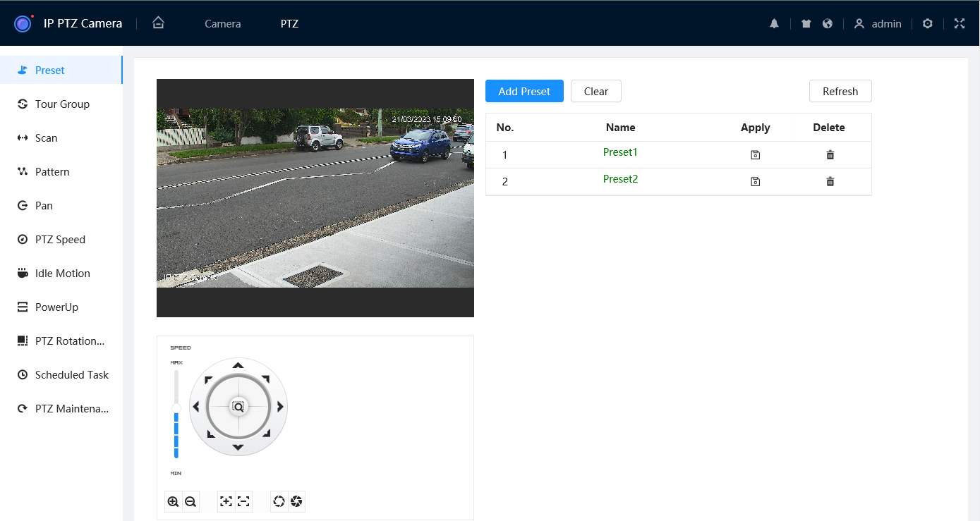
- Click
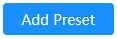 to add a new preset.
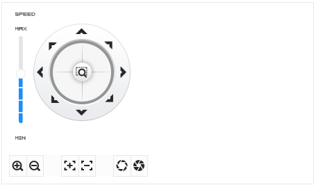
- Use the PTZ controls to position the camera where you would like to create a preset. Then click Save
 to save the preset position.
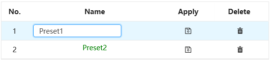
- Double-click on the preset Name to rename the preset to something descriptive (E.g. Front Gate), then press Enter
- Click Save
 .
. - Repeat Steps 1-4 to create as many presets as you require.
Presets (via Web Interface 3.0)
- Navigate to Setting > PTZ > Function > Preset.
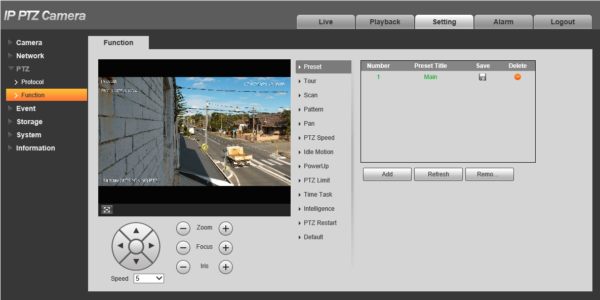
- Click
 to add a new preset
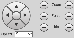
- Use the PTZ controls to position the camera where you would like to create a preset. Then click Save
 to save the preset position.
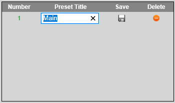
- Double-click on the preset title to rename the preset to something descriptive (E.g. Front Gate), then press Enter
- Click Save .
- Repeat Steps 1-4 to create as many presets as you require.
Presets (Via Black UI NVR)
-
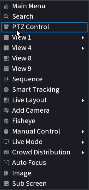
Right-click on the Live view Page

- Select PTZ Control.
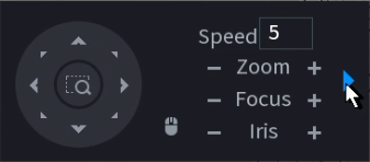
- Click the
 to open additional settings.
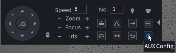
- Click the
 to open PTZ Config.
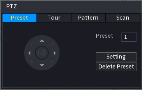
- Use the PTZ controls to move the PTZ to where you want to create the Preset.
- Click Setting to Save the Preset.
- For each additional Preset, increase the Preset Number by 1, then repeat steps 5 & 6.
- To edit a preset position, use the PTZ controls to move the PTZ where you want the Preset, enter the Preset Number of the Preset, then click Setting.
- To Delete a Preset, type the number of the Preset into the Preset Number, and click Delete Preset.
Tours
A Tour is a collection of presets that the PTZ moves between automatically. It can be configured via the PTZ's Web interface or an NVR.
Tours (via Web Interface 5.0)
- Navigate to Setting > PTZ > Tour Group.
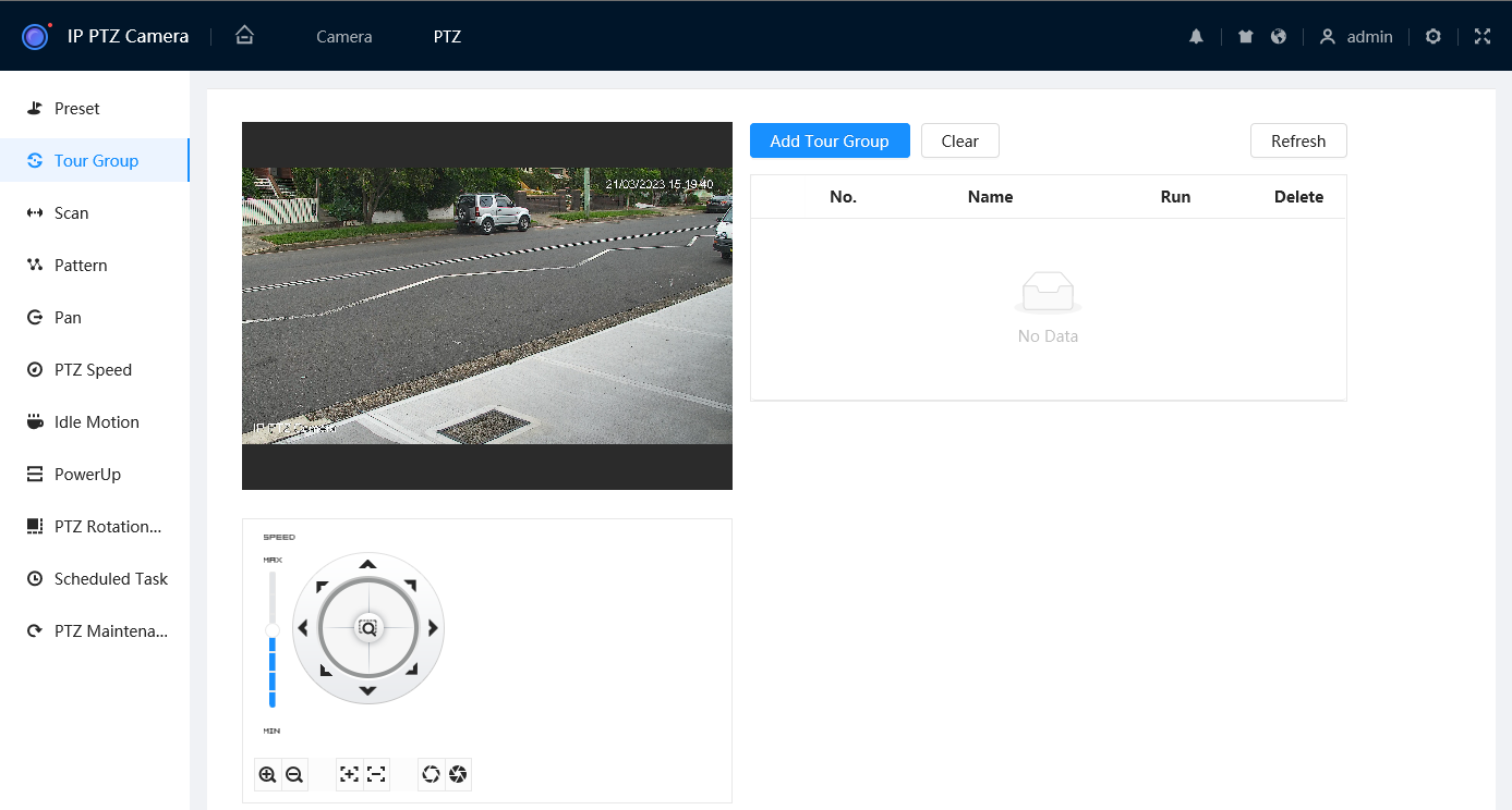
- Select
 to add a Tour.
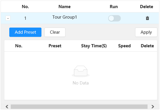
- Select
 to add a Preset to the Tour.
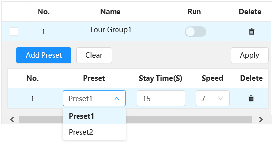
- Select the Preset from the Preset drop down list, then adjust the Stay Time(S) (How long it stays on this preset for) and Speed (Speed of the camera when changing between presets) if required.
- Repeat steps 3-4 for each Preset.
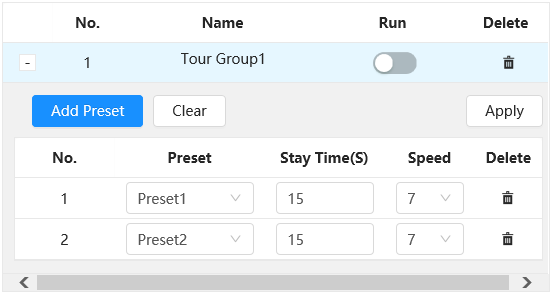
- Select
 to save your changes.
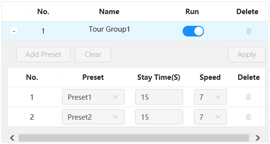
- Toggle Run to On
 to the start the Tour.
Tours (via Web Interface 3.0)
- Navigate to Setting > PTZ > Function > Tour
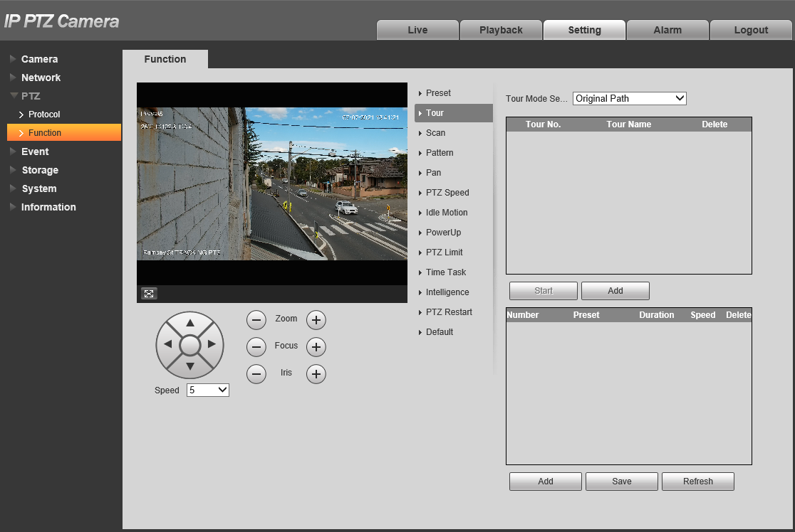
- Follow the previous steps to create the presets your PTZ will switch between.
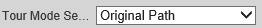
- Set the Tour Mode Select. This will apply to all tours.
Original Path: The PTZ camera moves in the order of the selected presets.
Shortest Path: The PTZ camera ranks presets by distance, and moves in an optimal path.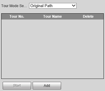
- Click
 to add a new tour.
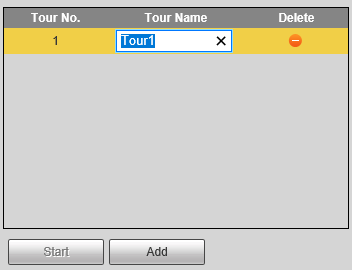
- Double-click on the tour name to rename the tour to something descriptive (E.g. Driveway Patrol), then press Enter.
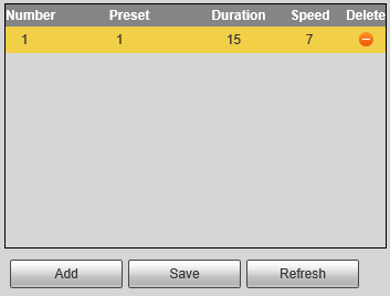
- Click
 to add a preset to the tour.
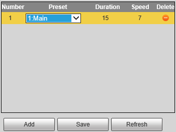
- Double click on the preset number to select the preset you want to use.
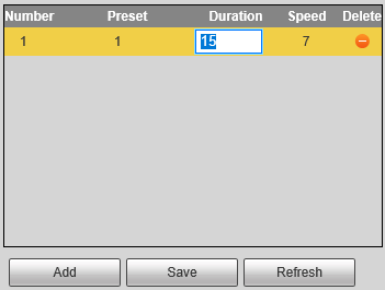
- Double click on the duration to change it (15 is the lowest value). The duration is how long the PTZ will stay on that preset for.
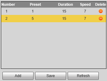
- Repeats Steps 6-8 for each preset you want to add to the tour. Click
 when done.
Tours (via Black UI NVR)
-
Right-click on the Live view Page

- Select PTZ Control.
- Click the to open additional settings.
- Click the to open PTZ Config.
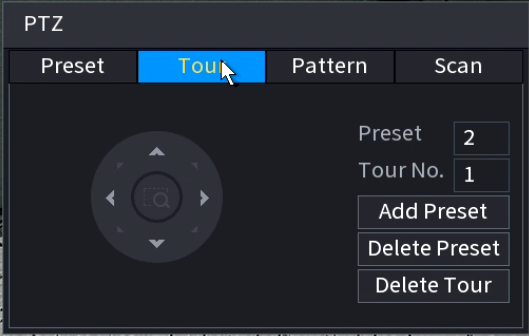
- Click Tour.
- Set the Tour No. of the Tour you will be creating. I.e. if it is the first tour created, set it to 1.
- Add a Preset to the Tour. Enter the number of the Preset, then click Add Preset. Repeat for each preset.
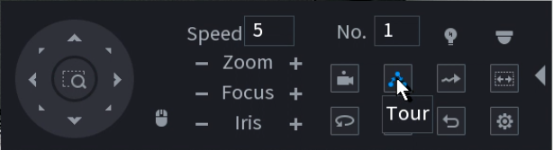
- To start the Tour enter the tour number into the No. box, then click the Tour Button.
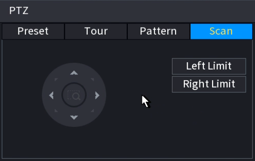
Scans
A Scan makes the PTZ move left and right between set boundaries at a set speed. It can be configured via the PTZ's Web interface or an NVR.
Scans (via Web Interface 5.0)
- Navigate to Setting > PTZ > Scan

- Select
 to add a Scan.
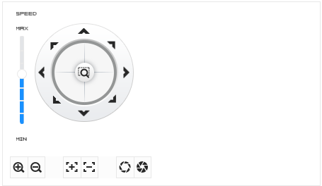
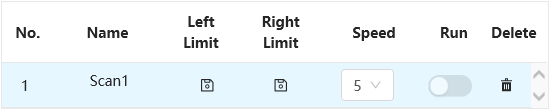
- Use the PTZ Controls to position the PTZ to where you want the left limit to be, then press
 under Left Limit.
 - Use the PTZ Controls to position the PTZ to where you want the right limit to be, then press under Right Limit.
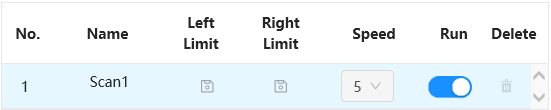
- Toggle Run to On to start the Scan.
Scans (via Web Interface 3.0)
- Navigate to Setting > PTZ > Function > Scan
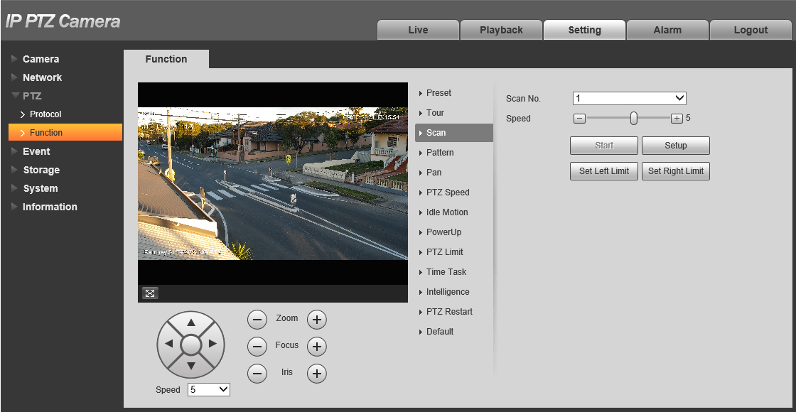
- Click

- Use the PTZ controls to move the PTZ to where you want the left limit to be, then click
- Use the PTZ controls to move the PTZ to where you want the right limit to be, then click


- Set the Speed. 5 is the default.
- Click Start to start the scan, click Stop to stop the scan.
Scans (via Black UI NVR)
-
Right-click on the Live view Page

- Select PTZ Control.
- Click the to open additional settings.
- Click the to open PTZ Config.
- Click Scan.
- Use the PTZ Controls to move the PTZ to where you want the Left Limit to be, then press
 .
. - Use the PTZ Controls to move the PTZ to where you want the Right Limit to be, then press
 .
.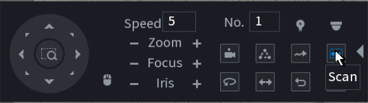
- Set the Speed and then press the Scan button to start the Scan.
Patterns
A Pattern is a recorded series of pan, tilt and zoom movements that will be performed on repeat. It can only be configured via the PTZ's Web interface.
Patterns (via Web Interface 5.0)
- Navigate to Setting > PTZ > Pattern.
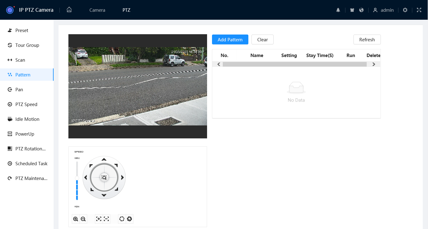
- Select
 to add a Pattern.
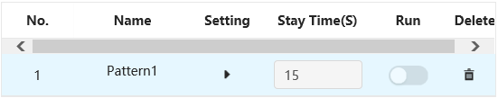
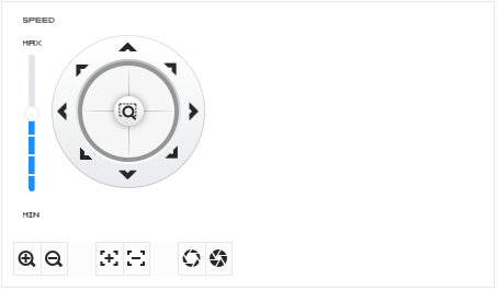
- Select Start Record
 then use the PTZ controls to move/zoom the PTZ in the pattern you wish it to follow, then select Stop Record
  to save the pattern.
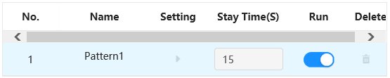
- Toggle Run to On to start the Pattern.
Patterns (via Web Interface 3.0)
- Navigate to Setting > PTZ > Function > Pattern
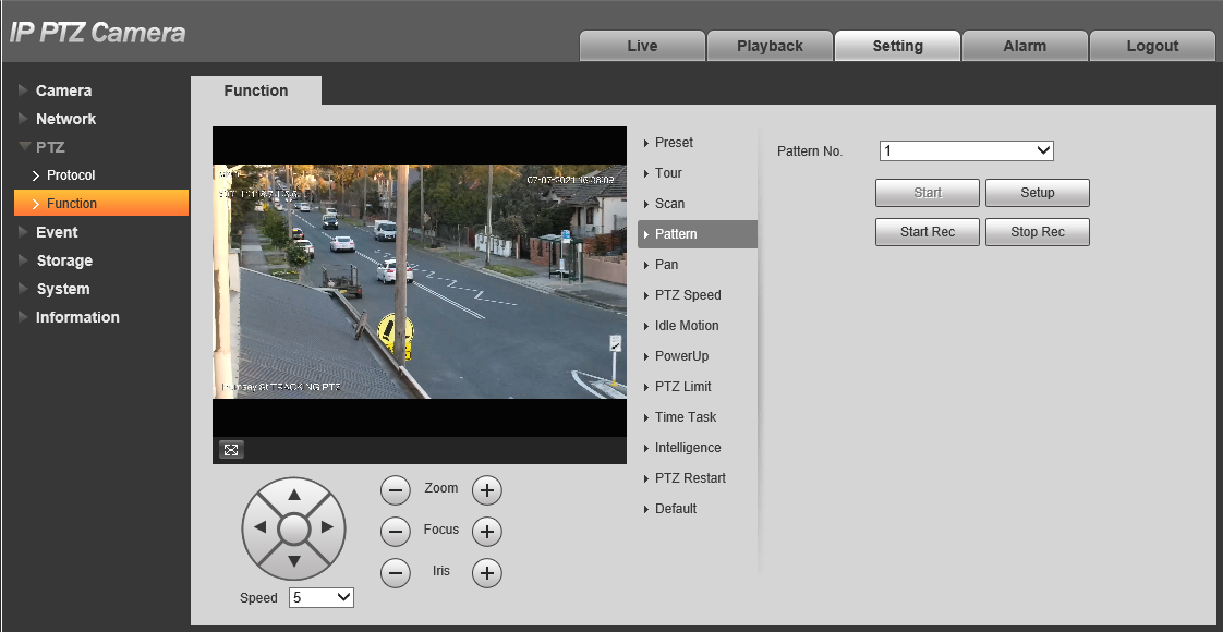
- Click

- Use the PTZ controls to position the PTZ where you want to start the pattern.
- Press

- Use the PTZ controls to move/zoom the PTZ in the pattern you wish it to follow
- Press

- Press Start to start the pattern, press Stop to stop the pattern.
Pans
A Pan moves the PTZ 360° at a set speed. It can be configured via the PTZ's Web interface or an NVR.
Pans (via Web Interface 5.0)
- Navigate to Setting > PTZ > Pan.
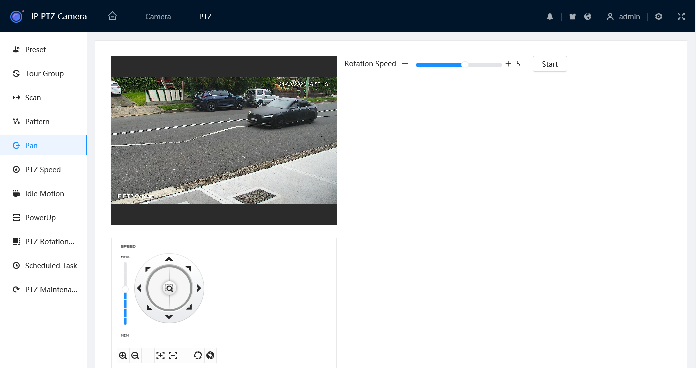
- Set the Rotation Speed. 5 is the default.
- Click Start
 to start the pattern, press Stop
  to stop the pattern.
Pans (via Web Interface 3.0)
- Navigate to Setting > PTZ > Function > Pan
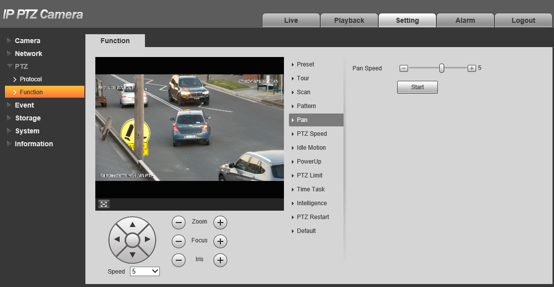
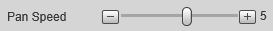
- Set the Pan Speed. 5 is the default.
- Click Start to start the pattern, press Stop to stop the pattern.
Pans (Via Black UI NVR)
-
Right-click on the Live view Page.

- Select PTZ Control.
- Click the to open additional settings.
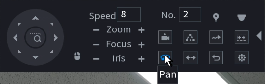
- Click the Pan button to start the Pan. Adjust the Speed if necessary.
Idle Motion, PowerUp and Time Task
Once you've configured a Preset, Tour, Scan or Pattern you can then choose to configure Idle Motion and PowerUp behaviour and/or a Time Task. They can only be configured in the Web Interface.
Idle Motion - Set the PTZ to automatically start a specific function (Preset, Tour, Scan or Pattern) when the PTZ does not receive any commands after a set period of time.
PowerUp - Set the PTZ to automatically start a specific function (Preset, Tour, Scan or Pattern) when it powers on.
Time Task/Scheduled Task - Set the PTZ to perform a set function (Preset, Tour, Scan or Pattern) during a set period.
Idle Motion (Web Interface 5.0)
-
Navigate to Setting
 > PTZ > Idle Motion.
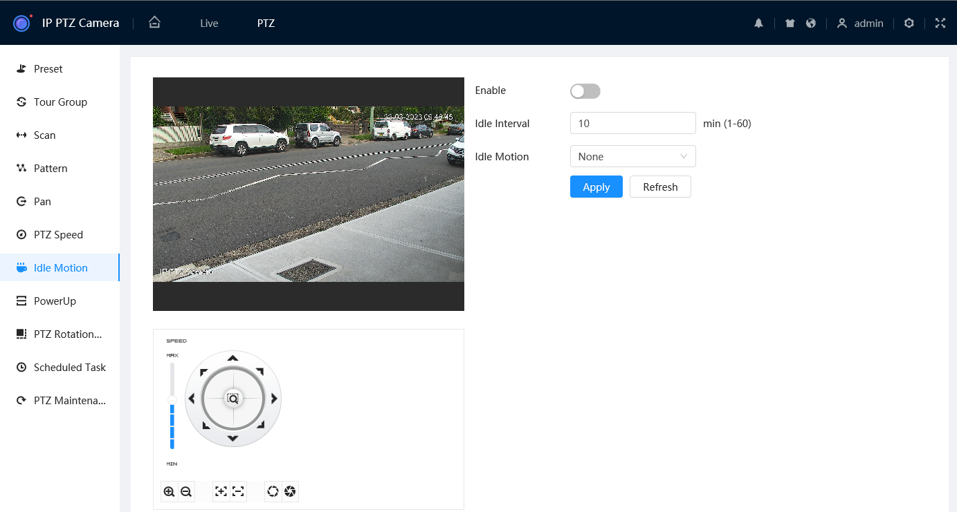
- Toggle Enable to On
 .
.
- Set the Idle Interval. This value is for how long the camera has to be inactive for before starting the Idle Motion action.
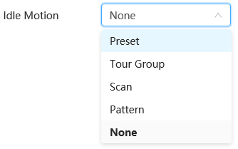
- Set the Idle Motion type (Preset/Tour/Scan/Pattern).
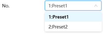
- Set the No. to the specific Preset/Tour/Scan/Pattern you want to use.
- Select
 to save your changes.
Idle Motion (Web Interface 3.0)
Idle Motion is used to set the PTZ to automatically start a specific function (Preset, Tour, Scan or Pattern) when the PTZ does not receive any commands after a set period of time. For example, you can have the PTZ return to a set preset if the PTZ is not moved for 1 minute.
- Navigate to Setting > PTZ > Function > Idle Motion
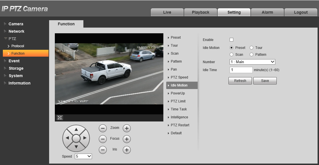

- Tick the Enable Checkbox
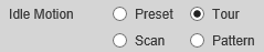
- Select the Idle Motion Type (Preset/Tour/Scan/Pattern).

- Set the Number to the specific Preset/Tour/Scan/Pattern you want to use.

- Set the Idle Time.
- Click
 .
.
PowerUp (Web Interface 5.0)
PowerUp is used to set the PTZ to automatically start a specific function (Preset, Tour, Scan, Pattern or Pan) when the PTZ powers on.
- Navigate to Setting > PTZ > PowerUp.
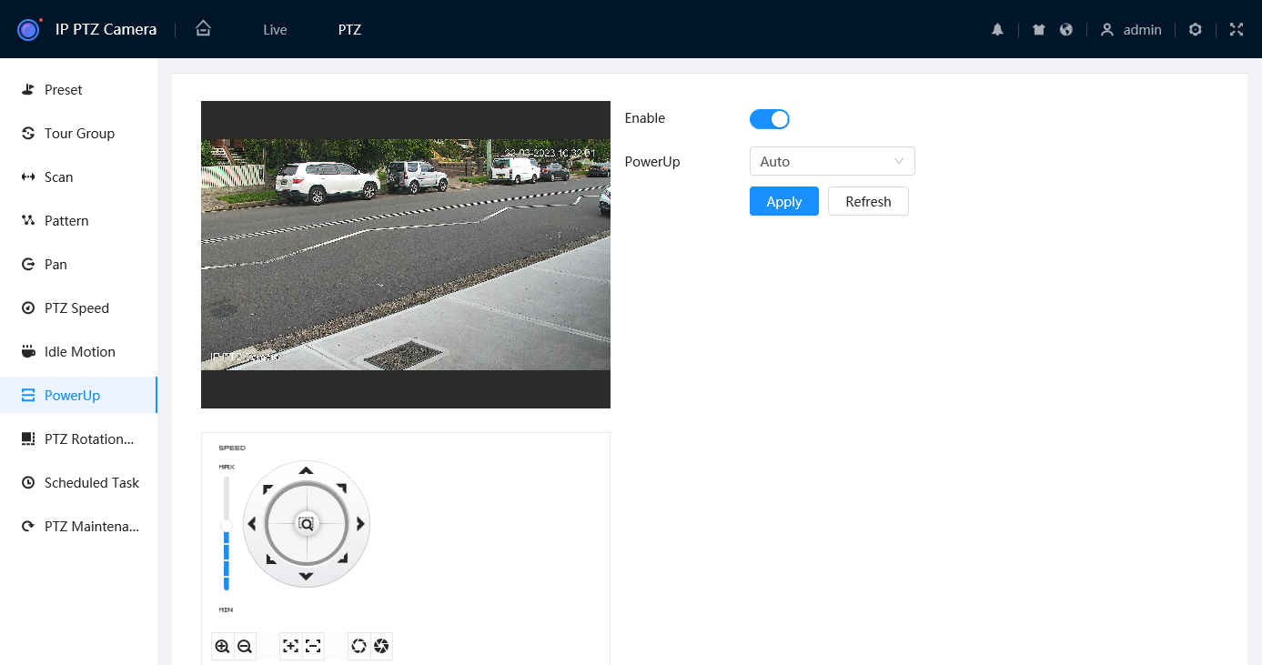
- Toggle Enable to On.
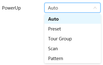
- Set the PowerUp Type. Auto will perform the last action the PTZ took.
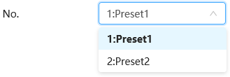
- Set the No. to the specific Preset/Tour/Scan/Pattern you want to use.
- Select to save your changes.
PowerUp (Web Interface 3.0)
PowerUp is used to set the PTZ to automatically start a specific function (Preset, Tour, Scan, Pattern or Pan) when the PTZ powers on.
- Navigate to Setting > PTZ > Function > PowerUp.
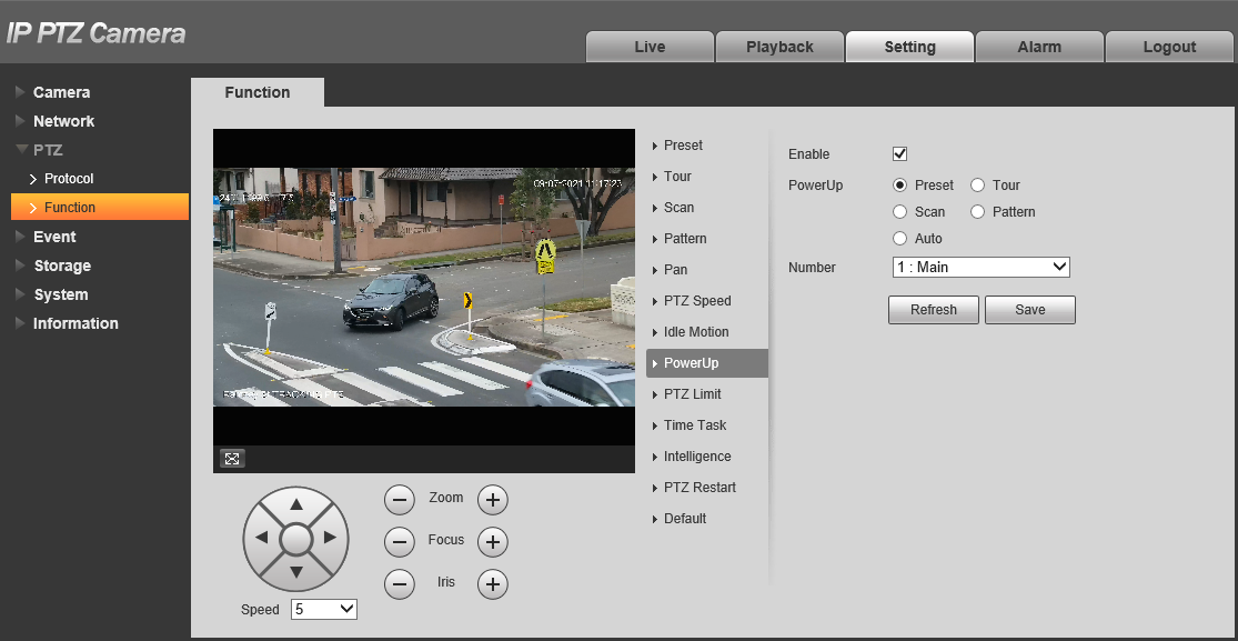
- Tick the Enable Checkbox
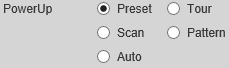
- Select the Idle Motion Type (Preset/Tour/Scan/Pattern). Auto will perform the last action the PTZ took.
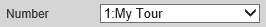
- Set the Number to the specific Preset/Tour/Scan/Pattern you want to use.
- Click .
Time Task/Scheduled Task (Web Interface 5.0)
Time Task/Scheduled Task is used to set the PTZ to perform a set function (Preset, Tour, Scan or Pattern) during a set period. 4 individual time tasks can be created.
-
Navigate to Setting > PTZ > Scheduled Task.
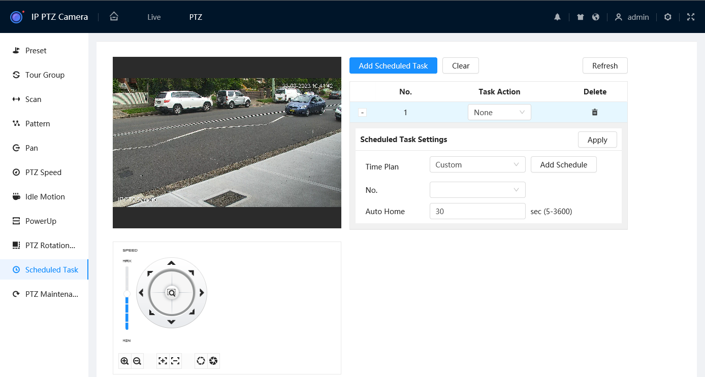
- Select
 to add a scheduled task.
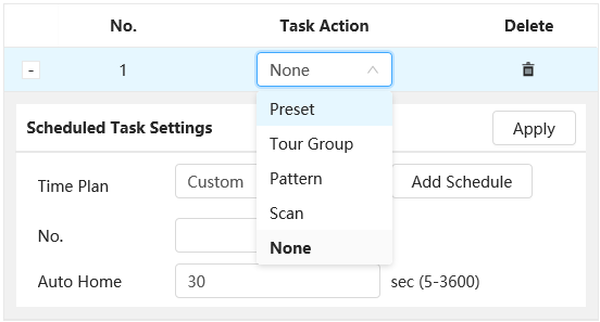
- Select the Task Action (Preset/Tour/Scan/Pattern).
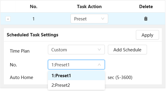
- Set the No. to the specific Preset/Tour/Scan/Pattern you want to use.
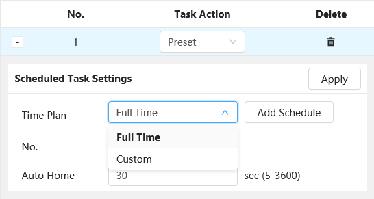
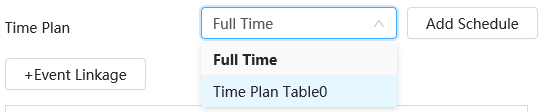
- Select the Time Plan you wish to use, or
 to add a custom Time Plan.
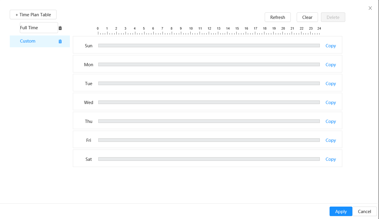
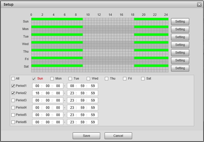
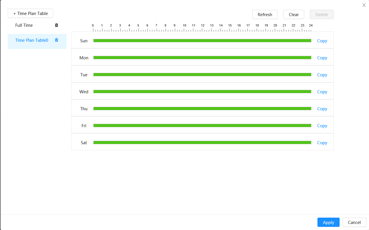
- Select the Custom Time Plan to amend it, or select
 to add a new one.
 - Click and drag on each day to add the hours you want the task to be active for. Green indicates hours the task will be active.
- Select
 to save the Schedule.
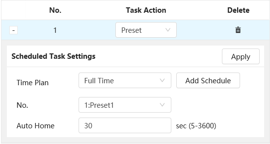
- Select the Custom Time Plan to amend it, or select
- Set Auto Home if required. Auto Home functions similarly to idle motion. It will set the PTZ to return to performing the Time Task if the Time Task is manually stopped (E.g. if the PTZ is moved manually via the PTZ controls).
Time Task/Scheduled Task (Web Interface 3.0)
Time Task/Scheduled Task is used to set the PTZ to perform a set function (Preset, Tour, Scan or Pattern) during a set period. 4 individual time tasks can be created
- Navigate to Setting > PTZ > Function > Time Task
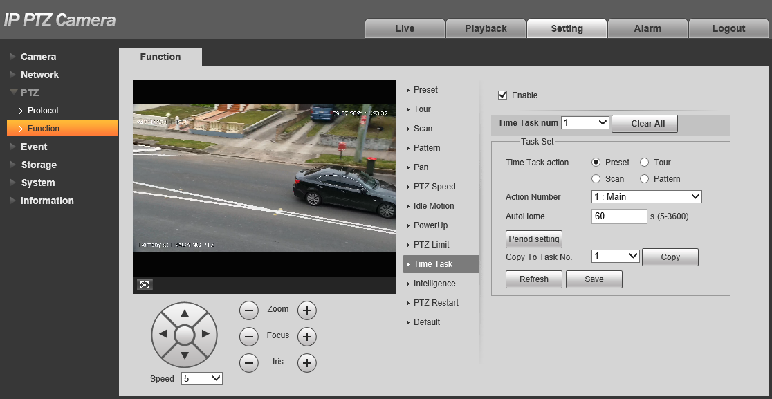

- Select the Time Task num you wish to configure.

- Tick the Enable Checkbox.
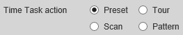
- Set the Time Task Action.

- Set the Action Number to the specific Preset/Tour/Scan/Pattern you want to use.
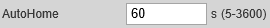
- Set Auto Home if required. Auto Home functions similarly to idle motion. It will set the PTZ to return to performing the Time Task if the Time Task is manually stopped (E.g. if the PTZ is moved manually via the PTZ controls).
- Click

- Configure the period the Time Task to be performed in. Click
 .
. - Click
 .
.
Motion Detection & Smart Motion Detection
Motion Detection
Motion Detection is triggered when the is any movement above the threash hold in the detection area. There is no distinction between targets.
Motion Detection is Required to be enabled from SMD.
NVR (Black GUI)
- Navigate Main Menu > Event > Alarm > Video Detection.
- Select the channel you want to Enable motion detection on with the drop down menu.
- After this you can choose to toggle motion detection sensitivity and area by selecting Region Settings.
- Click Apply to confirm settings.

NVR (Blue GUI)
- Go to Main Menu > Event.
- Select the Channel number of the camera you want to enable Motion Detection on.
- Tick Enable, then click OK.

Additional Settings
| Parameter | Description |
| Anti-Dither | Sets the Camera to only record one motion detection event in the set period. |
| Record | Enable this option if you wish for the camera to record when motion is detected. This requires Motion to be scheduled under Storage > Schedule > Record, and Auto to be selected for Record Mode under Storage > Record Control. |
| Record Delay | How long the camera will continue to record as part of the "motion event" after motion has stopped being detected |
| Relay-out | Enabling this will cause the relay of the camera to trigger when Motion is detected. |
| Alarm Delay | How long the relay will stay triggered for after motion is detected. Requires Relay-out to be enabled. |
| Send Email | Send an Email when Motion is detected. Requires configuration under Network > SMTP(Email) |
| PTZ | Set the PTZ to perform a configured Preset/Tour to Pattern when motion is detected. |
| Snapshot | A Snapshot will be taken when motion is detected. Motion Snapshots will need to be set in the Schedule under Storage > Schedule > Snapshot |
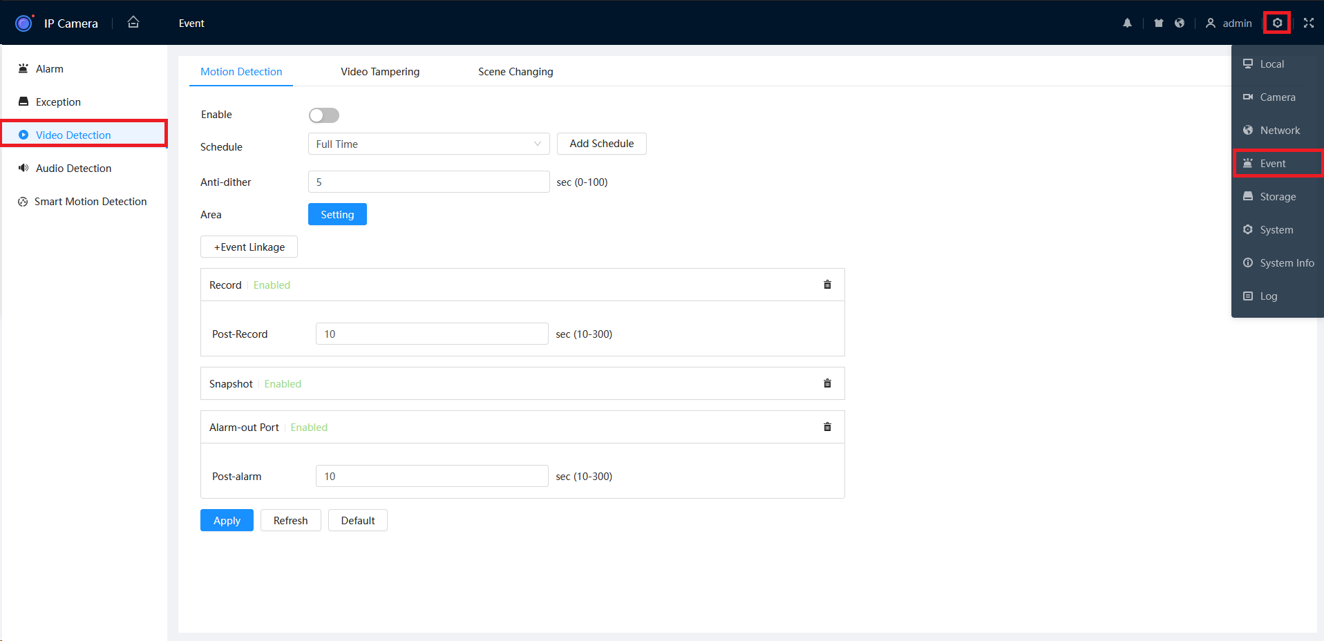
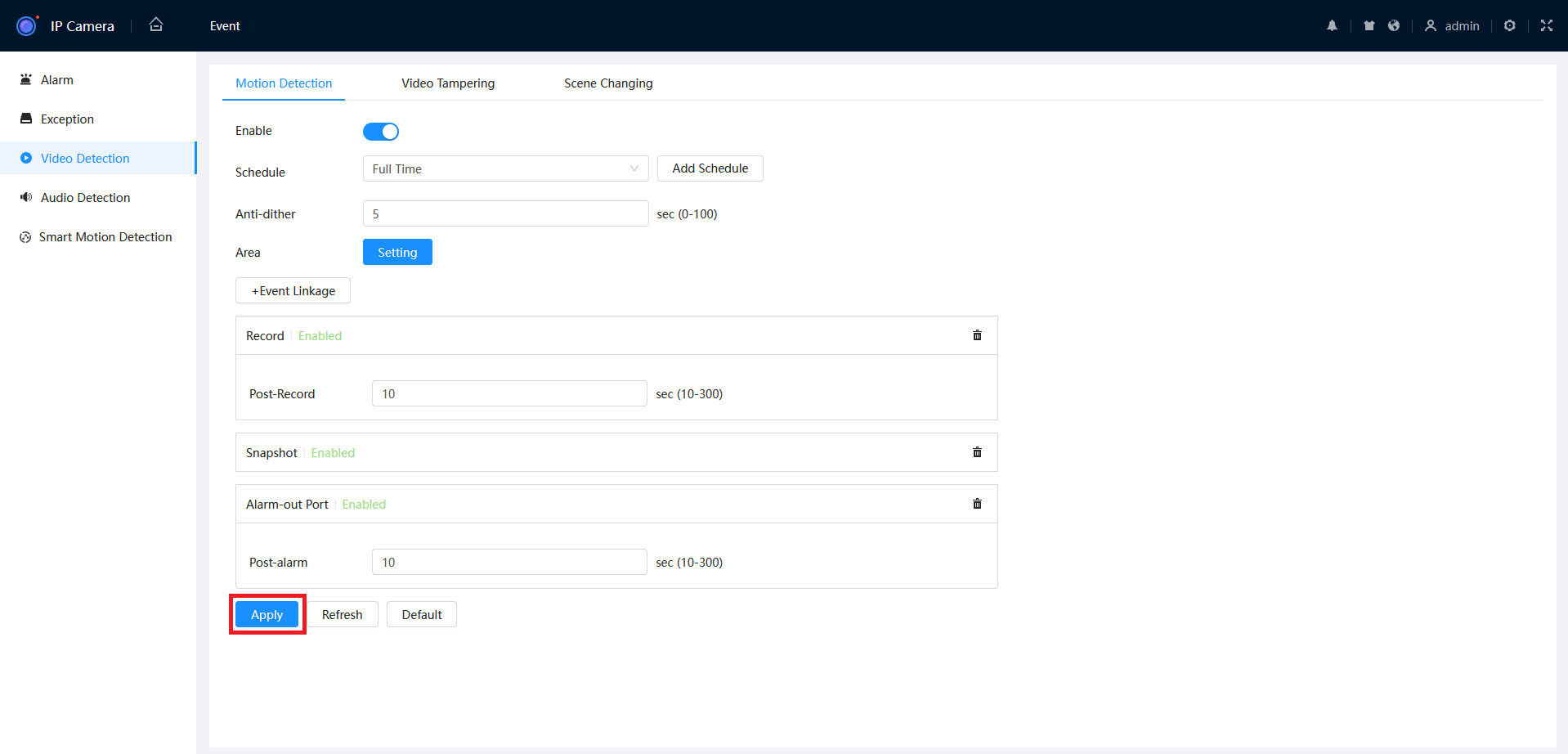
Camera Web Interface (Web 5.0)
- Navigate to Setting > Event > Video Detection > Motion Detection.
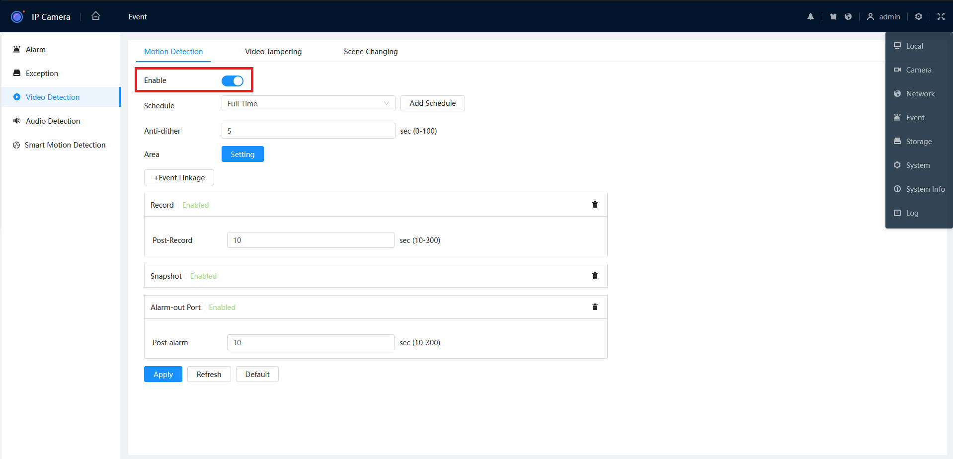
- Click the Enable switch to the on position (Blue).
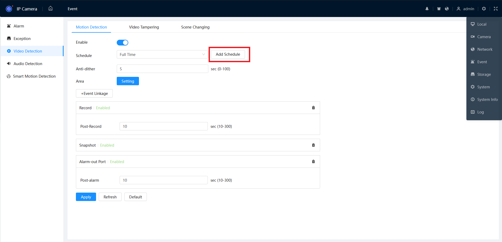
- If you only require motion during certain time periods, click Add Schedule.
- From the "Add Schedule" you can now configure the active period for Motion Detection. Once the desired times are set, click Apply.
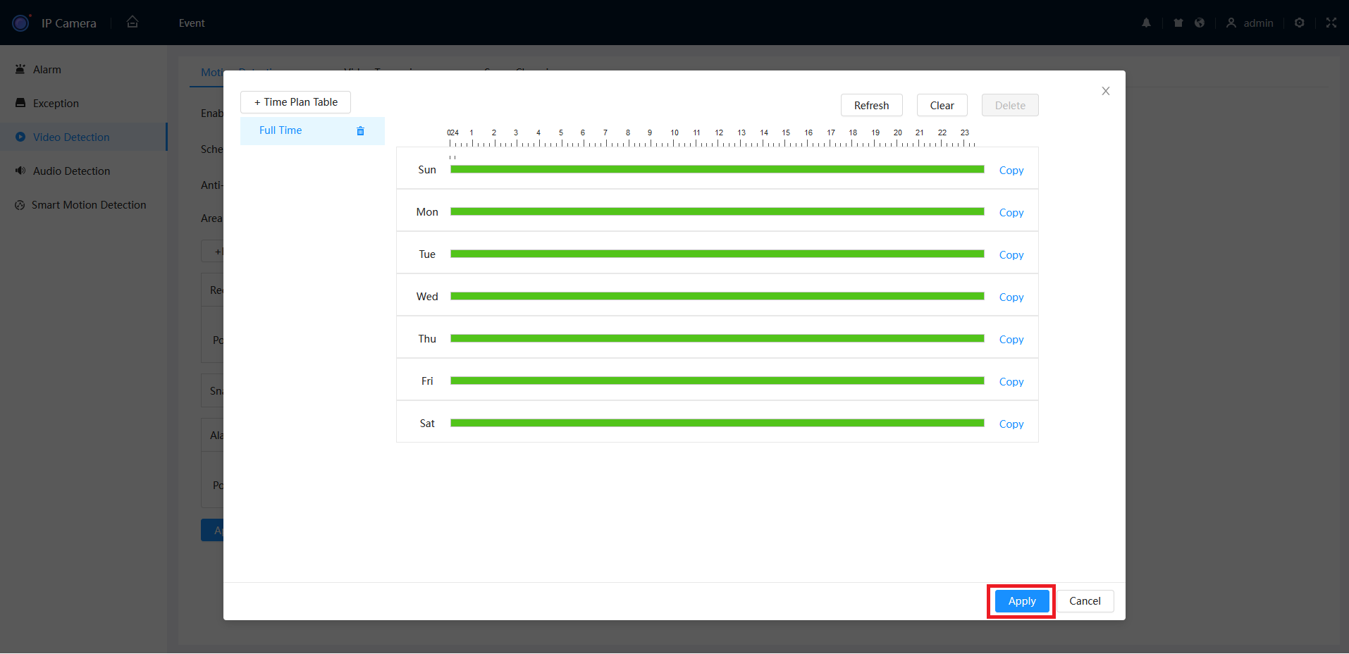
- Once the above steps are complete, click Apply.
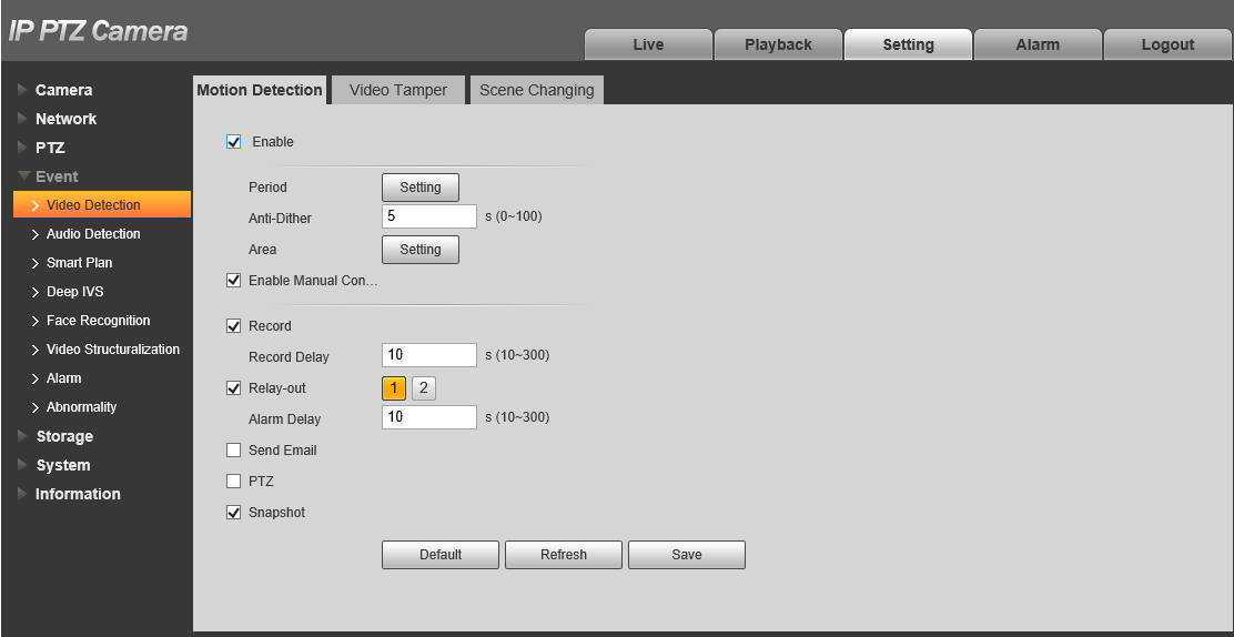
Camera Web Interface (Web 3.0)
- Navigate to Setting > Event > Video Detection > Motion Detection.
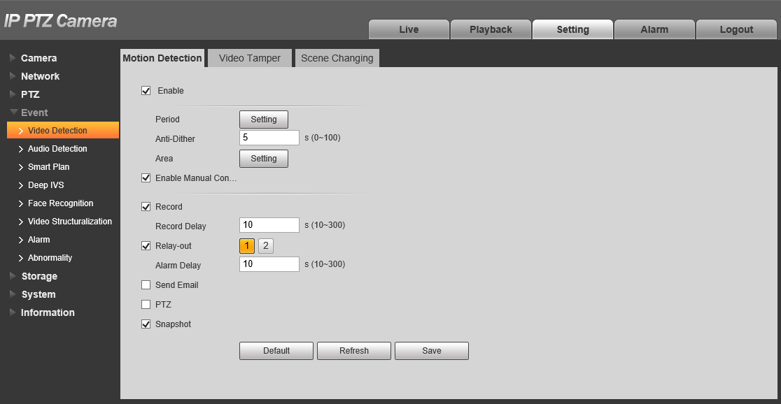

- Tick Enable to enable.
- If the camera is a PTZ, tick Enable Manual Control Trigger to exclude Motion Detection Event triggered by the PTZ being manually moved.
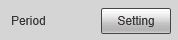
- Click
 next to Period to configure the active period for Motion Detection.
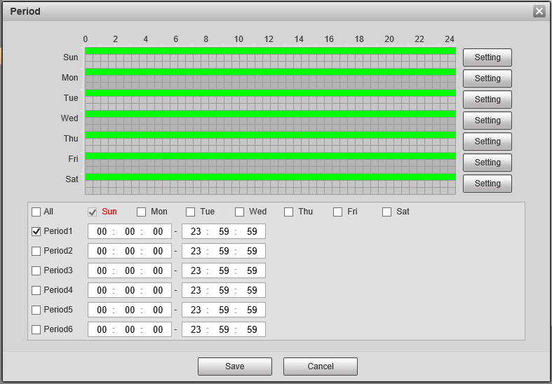
- Configure the schedule, then click
 .
. - Click
 .
.
Additional Settings
| Parameter | Description |
| Anti-Dither | Sets the Camera to only record one motion detection event in the set period. |
| Record | Enable this option if you wish for the camera to record when motion is detected. This requires Motion to be scheduled under Storage > Schedule > Record, and Auto to be selected for Record Mode under Storage > Record Control. |
| Record Delay | How long the camera will continue to record as part of the "motion event" after motion has stopped being detected |
| Relay-out | Enabling this will cause the relay of the camera to trigger when Motion is detected. |
| Alarm Delay | How long the relay will stay triggered for after motion is detected. Requires Relay-out to be enabled. |
| Send Email | Send an Email when Motion is detected. Requires configuration under Network > SMTP(Email) |
| PTZ | Set the PTZ to perform a configured Preset/Tour to Pattern when motion is detected. |
| Snapshot | A Snapshot will be taken when motion is detected. Motion Snapshots will need to be set in the Schedule under Storage > Schedule > Snapshot |
Smart Motion Detection (SMD)
Smart Motion Detection filters Motion Detection events to only active if the object that triggers it is a Human and/or a Vehicle. Motion Detection Must be enabled on the channel for SMD to function.
NVR (Black UI)
- Navigate Main Menu > Event > Ai Settings > SMD
- Select the Channel to apply Smart Motion Detection for, then click Enable.
- Set a Sensitivity level and Effective Targets will trigger it (Humans, Vehicles or both).
- Click Apply to confirm settings.

Camera Web Interface (Web 5.0)
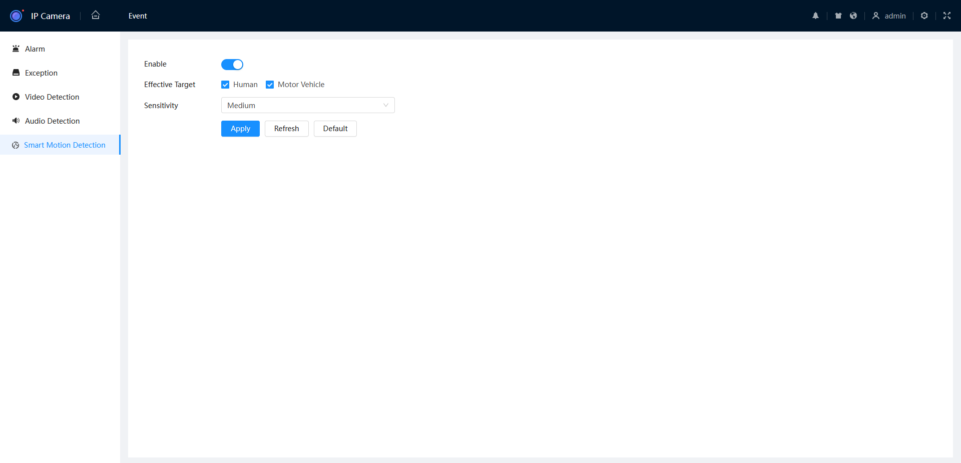
- Navigate to Setting > Event > Smart Motion Detection.

- Enable SMD, then click Apply.
Camera Web Interface (Web 3.0)
- Navigate to Setting > Event > Video Detection > Smart Motion Detection.
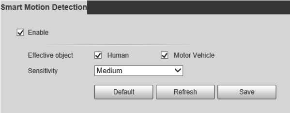
- Tick Enable to enable Smart Motion Detection.
- Tick Human and/or Motor Vehicle.
- Select the Sensitivity.
- Press
 to save your changes.
Additional Setup
Adjusting Trigger Actions
AI Trigger Actions
Event Trigger Actions Explained

-
Schedule: Sets the time when the rule is active and a trigger will occur.

Multiple IVS Rules on Single Camera
If creating multiple IVS rules on a Single camera that are scheduled for different times. Those Schedules must be configured in the Cameras Web interface.
- Anti Dither: The amount of time before an event will get triggered again.
-
Alarm-Out Port: Set if the Event will trigger the local alarm out put on the recorder/Camera

- Post-Alarm: The time the Alarm-out port will be Active for.
-
Show Message: Displays a Message on top of the live view that the Event has Occurred.

- Send Email: Will send the email with the event details. Requires configuration.
- Report Alarm: Sends Trigger Details to the Alarm Centre/Third party monitoring. Requires Configuration.
- Record Channel: Sets if the event will be recorded. (AI search, coloured on playback timeline).
- Post Record: Sets recording time after event occurred.
-
PTZ Linkage: Allows calling PTZ functions from other channels PTZ Linkage

- Tour: Starts a tour of selected channels.
- Picture Storage: Set if the event will take a snapshot of the event.
- Buzzer: Set if the NVR will Beep and event triggers.
- Log: If the Event will be Logged.
- Alarm Tone: Plays a designated .wav file in response to an event trigger. This can be imported via a USB flash drive to the NVR.
- Camera Audio: Selects to play Audio from active deterrent Camera.
-
Remote Warning Light: Select to set off Active deterrent lights.

Adjusting Motion Detection Sensitivity and Region
Adjusting Motion Detection Region & Sensitivity
If motion detection is triggering too easily, follow the below steps to adjust th...
If motion detection is triggering too easily, follow the below steps to adjust the sensitivity and region of detection.
Black GUI
- Go to Main Menu, then Alarm.
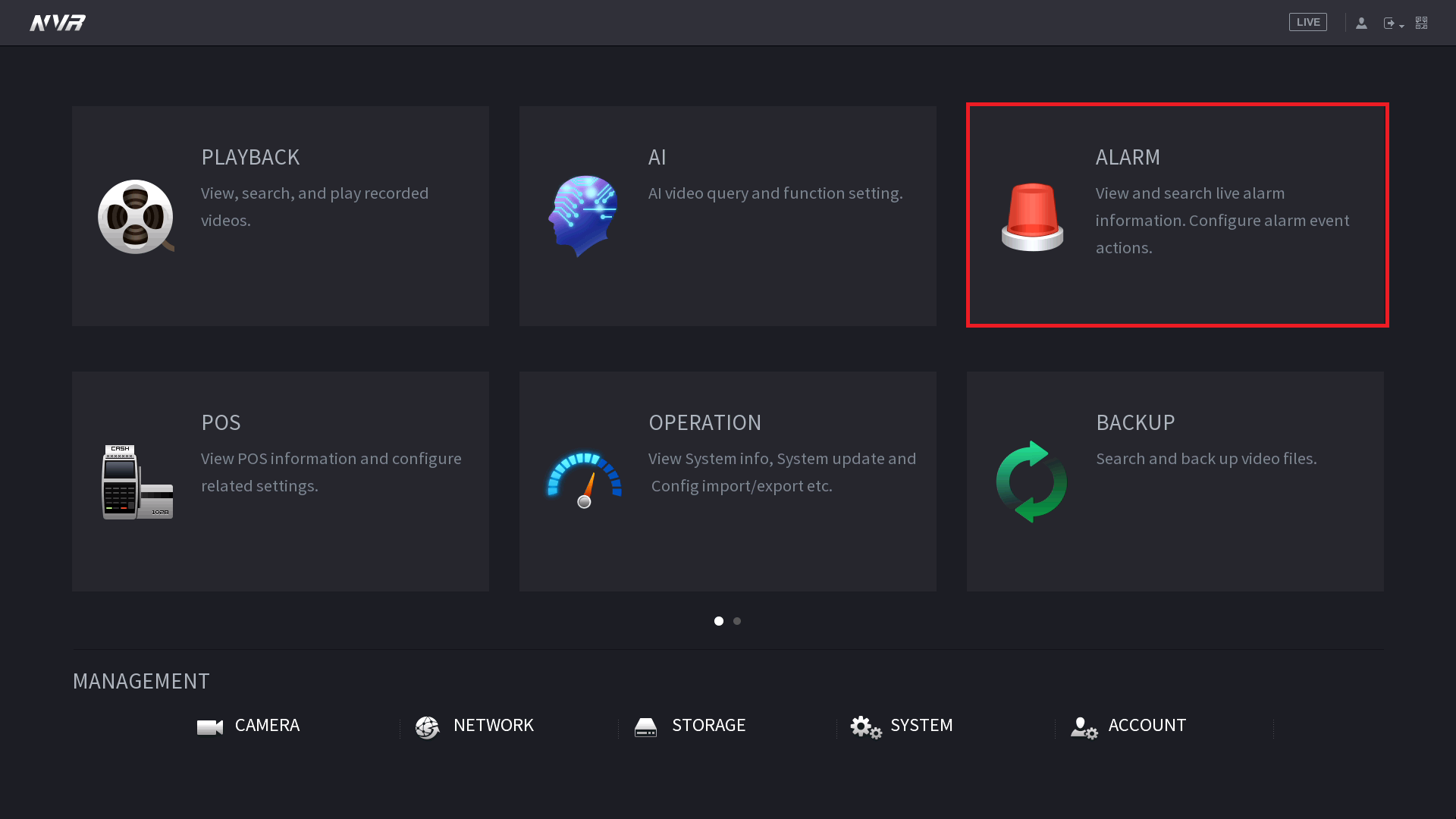
- On the left hand side select Video Detection. Select the Region Setting button.

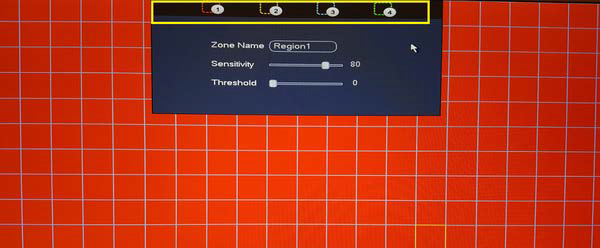
-
Adjust the Sensitivity and Threshold. There are multiple region settings if you wish to set different Sensitivity and Threshold settings for different parts of the image. Sensitivity is how easy it is to trigger (30-70 is recommended).Threshold is how much motion is required to trigger an event. (1-10 is recommended).

- Adjust the area of detection by clicking and dragging on the red squares. Red squares are where motion will be detected. Clear squares are where motion will not be detected. Right Click to exit, and select Apply.
Blue GUI
Go to Main Menu > Event > Video Detection > Motion Detection
- Click the Setup/Setting button next to Region to access the zone, sensitivity and threshold settings for motion detection.
- Adjust the Sensitivity & Threshold to suit your environment. High Sensitivity, Low Threshold mans it will be easy to trigger. Low Sensitivity, High Threshold means it is hard to trigger.
- Adjust the area of detection by clicking and dragging on the red squares. Red squares are where motion will be detected. Clear squares are where motion will not be detected. Right Click to exit, and select Apply.
Sensitivity: Determines how sensitive the zone is to movement. 1 being the lowest and 100 the highest. (30-70 is recommended)
Threshold: Determines the minimum size of an object that can trigger motion detection. 1 Being the lowest and 100 the highest (1-10 is recommended).
Camera Web Interface
- Navigate to Setting > Event > Video Detection > Motion Detection
- Click next to Period to configure the active period for Motion Detection.

- Configure the schedule, then click .
- Click next to Area to configure the active motion detection area and it's sensitivity.
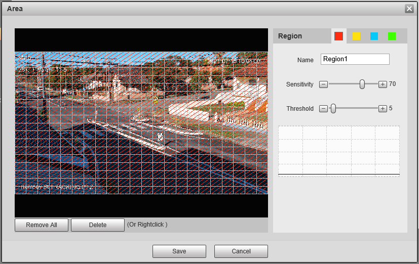
- Add/Remove the coloured squares to configure where motion will be detected. For example you may want to remove the coloured squares that overlap trees.
- Adjust Sensitivity & Threshold if necessary. There are four different colours so you can have four different settings.
Sensitivity is how easy it is to trigger 30-70 is recommended.
Threshold is how much has to move to trigger 1-10 is recommended.
High Sensitivity/Low Threshold will pick up motion easier, whereas Low Sensitivity/High Threshold will be harder to trigger. - Click .
IVS & Face Detection/Recognition
For a PTZ, IVS and Face detection are configured per Preset. They can be configured via the Web Interface of the PTZ, or via an NVR.
Tripwire - Draw a line. Detect when the target crosses the line in the defined direction.
Intrusion - Draw a shape. Detect when the target enters/exits the area or appears in the area.
Abandoned Object - Draw a shape. Detect if a target enters the area and stays longer than the set time.
Missing Object - Draw a shape. Detect if an object is removed from the scene longer than the set time.
Face Recognition - Compare face capture data to a list of previously captured faces, or uploaded image data.
Tripwire
Tripwire (via Web Interface 5.0)
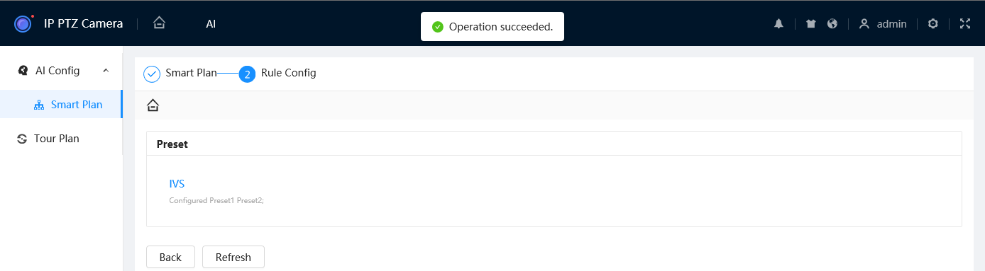
- Navigate to AI > AI Config > Smart Plan.
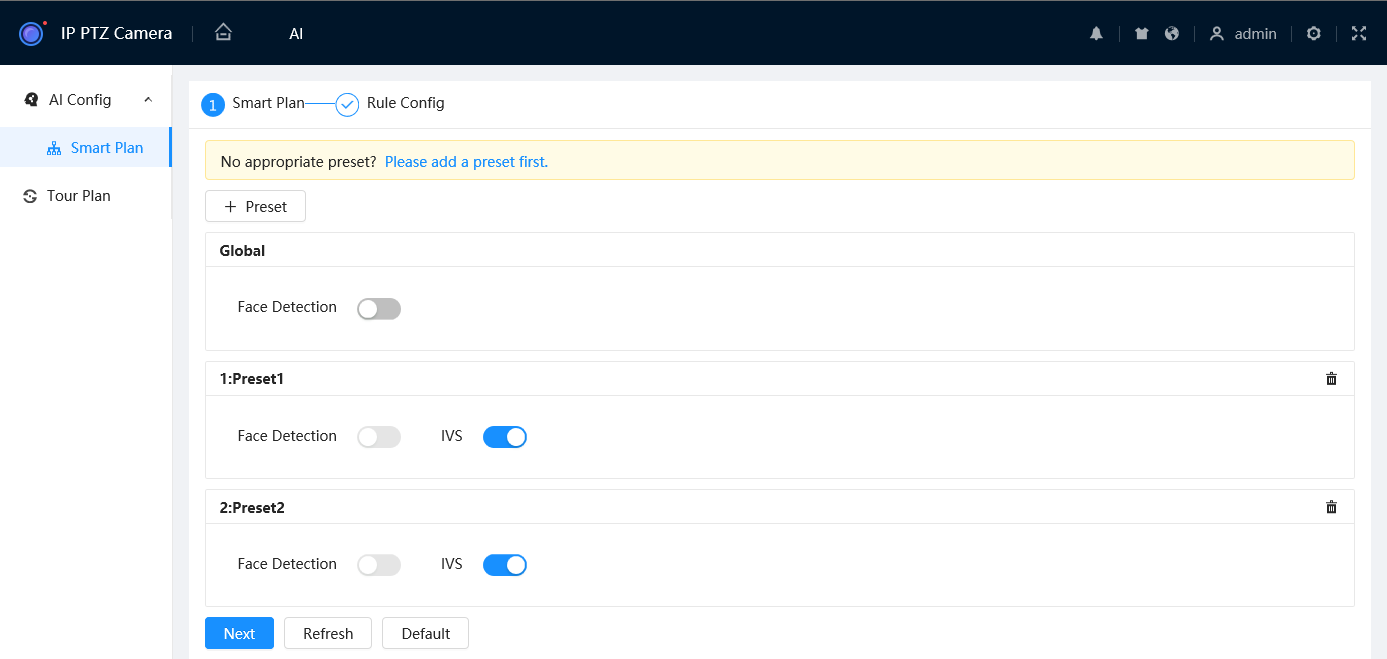
- Select
 and select the Preset you wish to add the Tripwire on.
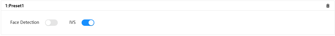
- Toggle IVS to On
 for the Preset you wish to add the Tripwire on.
 - Select

- Select
 .
.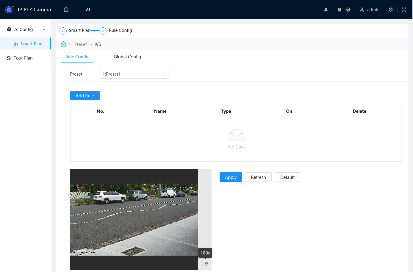
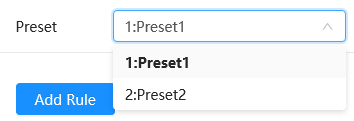
- Select the Preset you wish to add the Tripwire to.
- Select
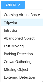
 , then choose Tripwire to add a Tripwire.
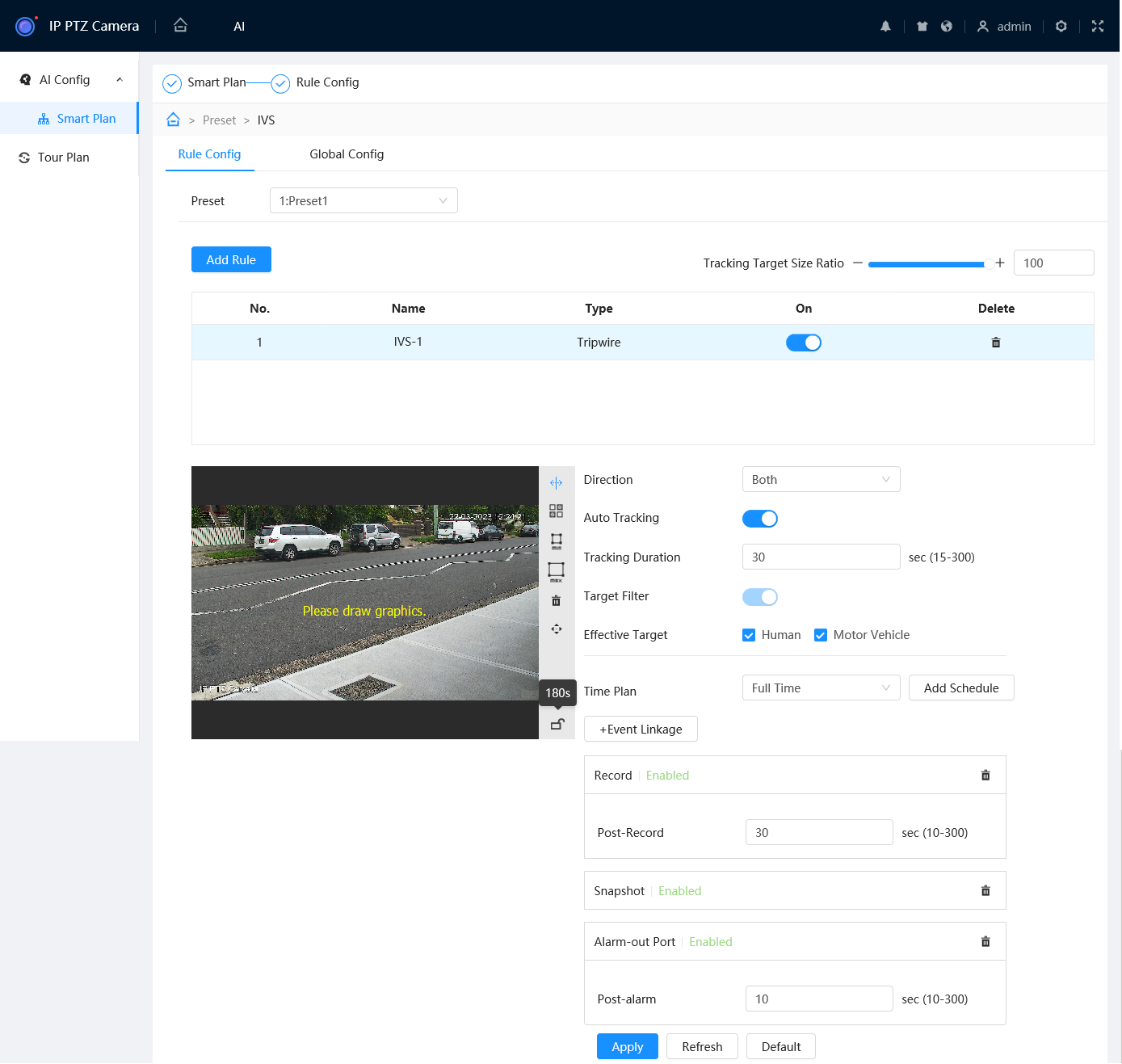
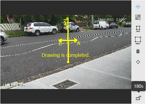
- Ensure
 is selected, then draw the Tripwire. Left-click on the camera feed to start drawing the Tripwire line. Left-click again to finish the line (optionally, you can add additional corners to the line by continuing to left click). Right-click to finish placing the line.
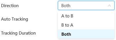
- Set the Direction. Both will do both directions, A to B and B to A will only trigger if the object moves in that direction (Depicted by an arrow on the camera feed).
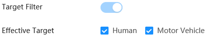
- Set the Effective Target (AI Camera only).
- (Optional) Select
 , then
  to add a custom Time Plan to change the active hours of the Tripwire. Adjust the timeline so the green sections are the active hours and white are the inactive hours you wish to use for the rule. Select
  to save your changes, then select the new Time Plan from the list.
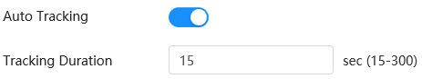
- (Optional) Enable Auto Tracking and set the Tracking Duration. This will allow the PTZ to zoom in and follow a target that triggers the Tripwire.
- (Optional) Use Min
 and Max
  to adjust the Min & Max filters. The Tripwire will only trigger if the target is between the Min and Max size.
- (Optional) Add event links (Send Email, Snapshot, Alarm-Out Port, etc) by selecting
 . These Events usually require additional setup.
 - Select
 to save your Tripwire
 - Repeat steps 7-12 for each Tripwire you wish to add.
Tripwire (via Web Interface 3.0)
- Navigate to Setting > Event > Smart Plan
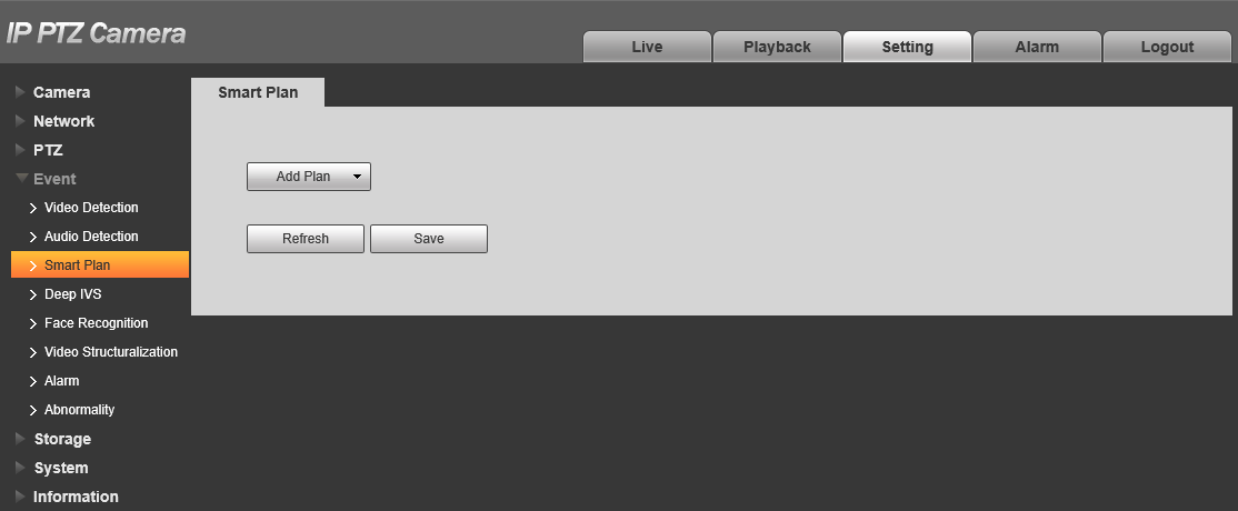
- Click Add Plan and select the Preset you wish to configure the tripwire on.

- Click Deep IVS.
- Click
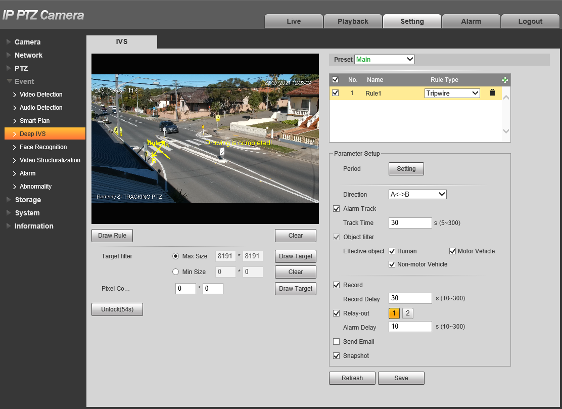
- Navigate to Setting > Event > Deep IVS

- Select the Preset you want to create the tripwire on.
- Click
 to add an IVS rule
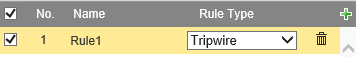
- Set the Rule Type to Tripwire.
- Click
 .
.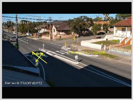
- Draw the Tripwire. Left-click on the camera feed to start drawing the Tripwire line. Left-click again to finish the line (optionally, you can add additional corners to the line by continuing to left click). Right-click to finish placing the line.
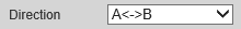
- Set the Direction of the Tripwire.
A<->B will do both directions
A will do A direction only (Depicted by an arrow on the camera feed)
B will do B direction only (Depicted by an arrow on the camera feed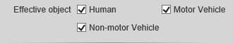
- Set the Effective object (AI Camera only).

- (Optional) Set the period by clicking
 .
. - Repeat steps 7-13 for each additional Tripwire you wish to add.
- Click
 .
.
Additional Settings
| Parameter | Description |
| Max Size/Min Size | Set the size range of targets. Targets larger than the max size, or smaller than the min size will not trigger the tripwire. |
| Lock/Unlock | Locks/Unlocks the PTZs position while IVS is being configured. |
| Alarm Track | Enable to set the PTZ with track the target when the tripwire is tripped. |
| Track Time | Set how long the PTZ will track for. Requires Alarm Track to be enabled. |
| Record | Enable this option if you wish for the camera to record when The tripwire is triggered. This requires IVS to be scheduled on an NVR under Storage > Schedule > Record, and Auto to be selected for Record Mode under Storage > Record Control. |
| Record Delay | How long the camera will continue to record as part of the "IVS event" after the event has finished. |
| Relay-out | Enabling this will cause the relay of the camera to trigger when the tripwire is triggered. |
| Alarm Delay | How long the relay will stay triggered for after the tripwire is triggered. Requires Relay-out to be enabled. |
| Send Email | Send an Email when the tripwire is triggered. Requires configuration under Network > SMTP(Email) |
| Snapshot | A Snapshot will be taken when the tripwire is triggered is detected. IVS Snapshots will need to be set in the Schedule under Storage > Schedule > Snapshot |
Tripwire (via NVR)
-
Right-click on the Live view Page

- Select PTZ Control.
- Click the to open additional settings.
- Click the to open PTZ Config.
- Use the PTZ controls to move the PTZ to where you want to create the Preset.
- Click Setting to Save the Preset.
- Right-Click to Exit the PTZ Control Menu.
-
Right-Click and select Main Menu.

- Select AI.
- Select Parameters > Smart Plan
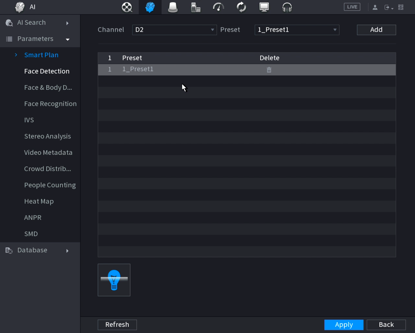
- Set the channel to the PTZ's channel.
- Set the Preset to the preset created earlier.
- Click Add.
- Select the IVS Option
 for Smart Plan.
 - Select Parameters > IVS.
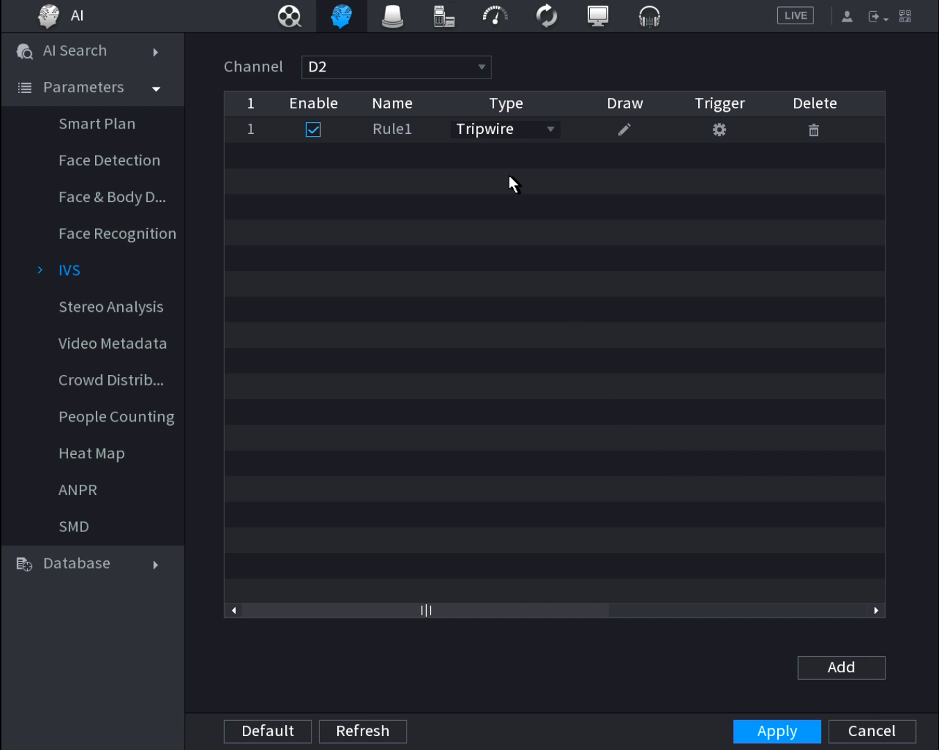
- Set the Channel to the PTZ's channel.
- Click
 .
.
- Set the Type to Tripwire.
- Click the Draw
 icon.
icon.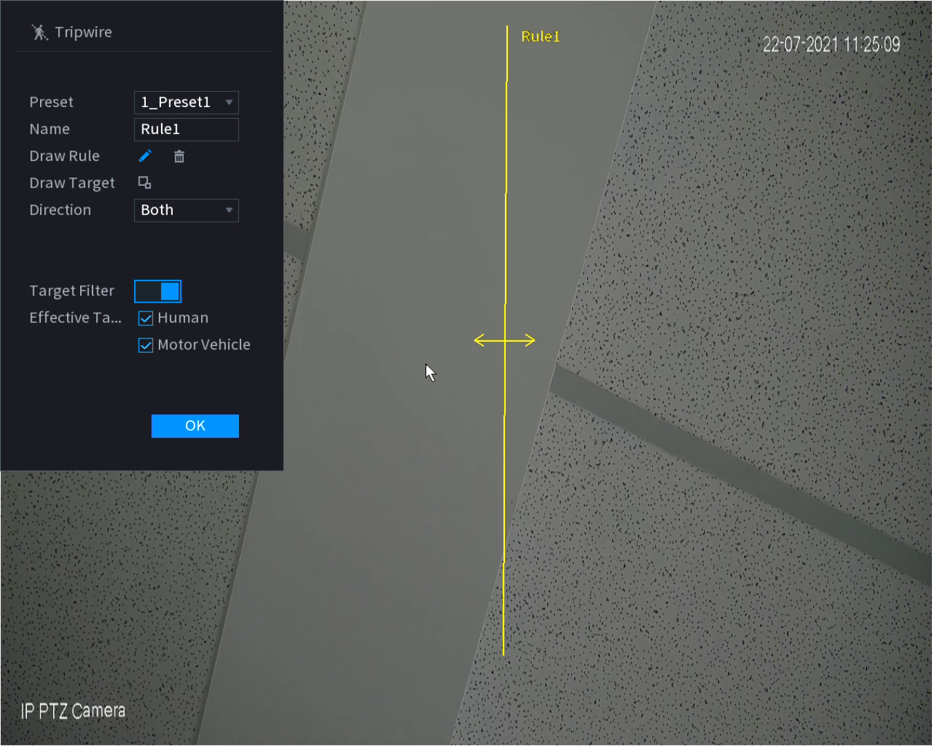
- Set Preset to the Preset created earlier.
- Select the Draw Rule
 Icon.
Icon. - Left-click on the camera feed to start drawing the Tripwire line. Left-click again to finish the line (optionally, you can add additional corners to the line by continuing to left click). Right-click to finish placing the line.
- Set the Direction the target must move to trigger the Tripwire.
Both will do both directions
A to B will only trigger in the direction from A to B only (Depicted by an arrow on the camera feed)
B to A will only trigger in the direction from B to A only (Depicted by an arrow on the camera feed) - (AI Cameras Only) Turn Target Filter On, and select Humans and/or Motor Vehicle. The Tripwire will only activate for the selected targets.
- (Optional) Set the Name of the Rule
- (Optional) Select Draw Target to configure the Min/Max size filters for the target.
- Click OK.
- Click Apply.
Additional settings
Click the Trigger Icon  to configure additional settings.
| Parameter | Description |
| Schedule | Schedule the active ours of the IVS rule. This will only work from the NVR if AI by NVR is used. |
| Alarm Out | Sets an external alarm to activate whenever a face is detected. |
| Post-Alarm | Sets how long the system waits after a trigger before detecting again (10 seconds by default) |
| Alarm Track | Enable to set the PTZ with track the target when the tripwire is tripped. |
| Report Alarm | Updates the alarm system status on the network (Unused for this system). |
| Send Email | Notifies a specified email address whenever the event is triggered (Requires internet connection & setup) |
| Record | Enable this option if you wish for a camera to record when The intrusion is triggered. Sets which camera to record to when the event is triggered. This requires IVS to be scheduled on an NVR under Storage > Schedule > Record, and Auto to be selected for Record Mode under Storage > Record Control. |
| Post-Record | How long the camera will continue to record as part of the "IVS event" after the event has finished. |
| PTZ Linkage | Set PTZ behaviours in response to a event trigger, such as selecting a Tour to perform, etc |
| Tour | Set Tour behaviours in response to a event trigger. |
| Buzzer | Sets the NVR to beep whenever an event is triggered |
| Log | Log IVS details in the Log (enabled by default) |
| Alarm Tone | Plays a designated .wav file in response to an event trigger. This can be imported via a USB flash drive to the NVR. |
| Auto Tracking | Enable to allow auto tracking. |
| Tracking Duration | Set how long the PTZ will track for. Requires Alarm Track to be enabled. |
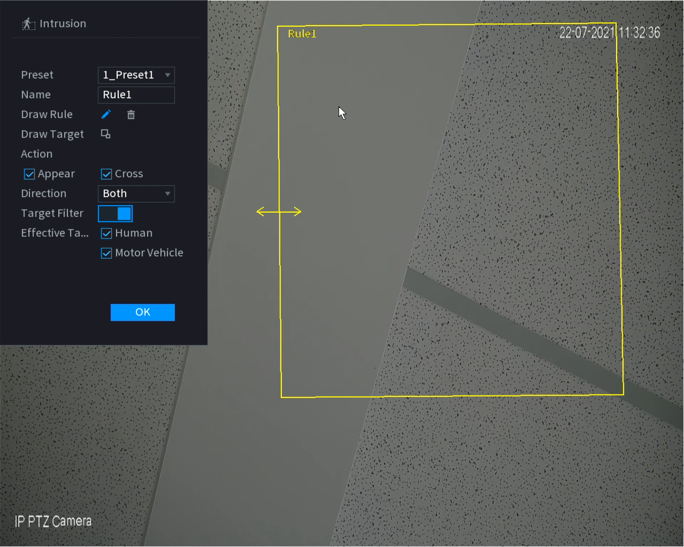
Intrusion
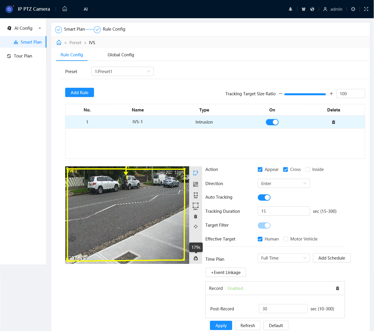
Intrusion (via Web Interface 5.0)
- Navigate to AI > AI Config > Smart Plan.
- Select and select the Preset you wish to add the Intrusion on.
- Toggle IVS to On for the Preset you wish to add the Intrusion on.
- Select
- Select .
- Select the Preset you wish to add the Intrusion to.
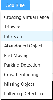
- Select , then choose Intrusion to add a Intrusion.
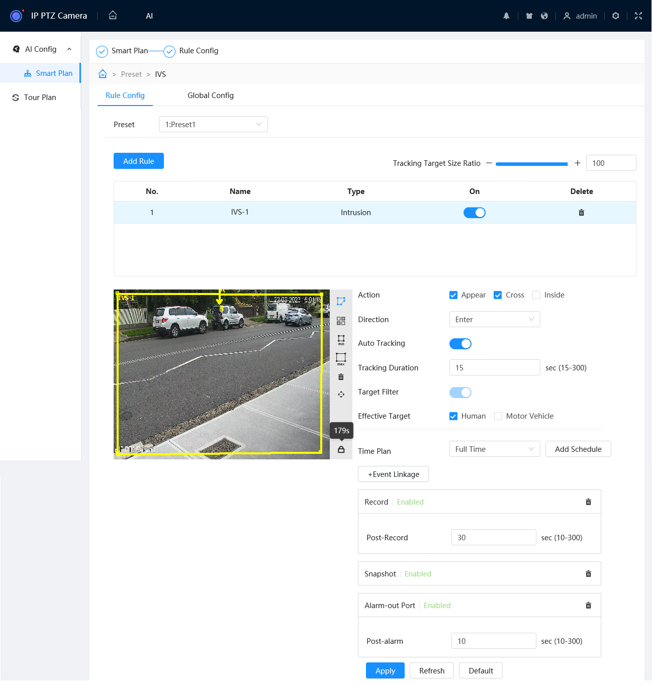
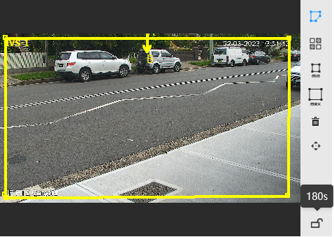
- Ensure is selected, then draw the Intrusion. Left-click on the camera feed to start drawing the Intrusion shape. Left-click to place additional corners. Right-click to finish placing the shape.

- Set the Action. Appears will trigger if the target appears inside the intrusion (E.g. if the intrusion covers an area with a door.) Cross will trigger if the target crosses the intrusion line.
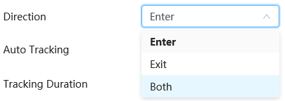
- If Cross was selected, set the Direction.
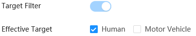
- Set the Effective Target (AI Camera only).
- (Optional) Select , then to add a custom Time Plan to change the active hours of the Intrusion. Adjust the timeline so the green sections are the active hours and white are the inactive hours you wish to use for the rule. Select to save your changes, then select the new Time Plan from the list.
- (Optional) Enable Auto Tracking and set the Tracking Duration. This will allow the PTZ to zoom in and follow a target that triggers the Tripwire.
- (Optional) Use Min and Max to adjust the Min & Max filters. The Intrusion will only trigger if the target is between the Min and Max size.
- (Optional) Add event links (Send Email, Snapshot, Alarm-Out Port, etc) by selecting . These Events usually require additional setup.
- Select to save your Intrusion
- Repeat steps 7-12 for each Intrusion you wish to add.
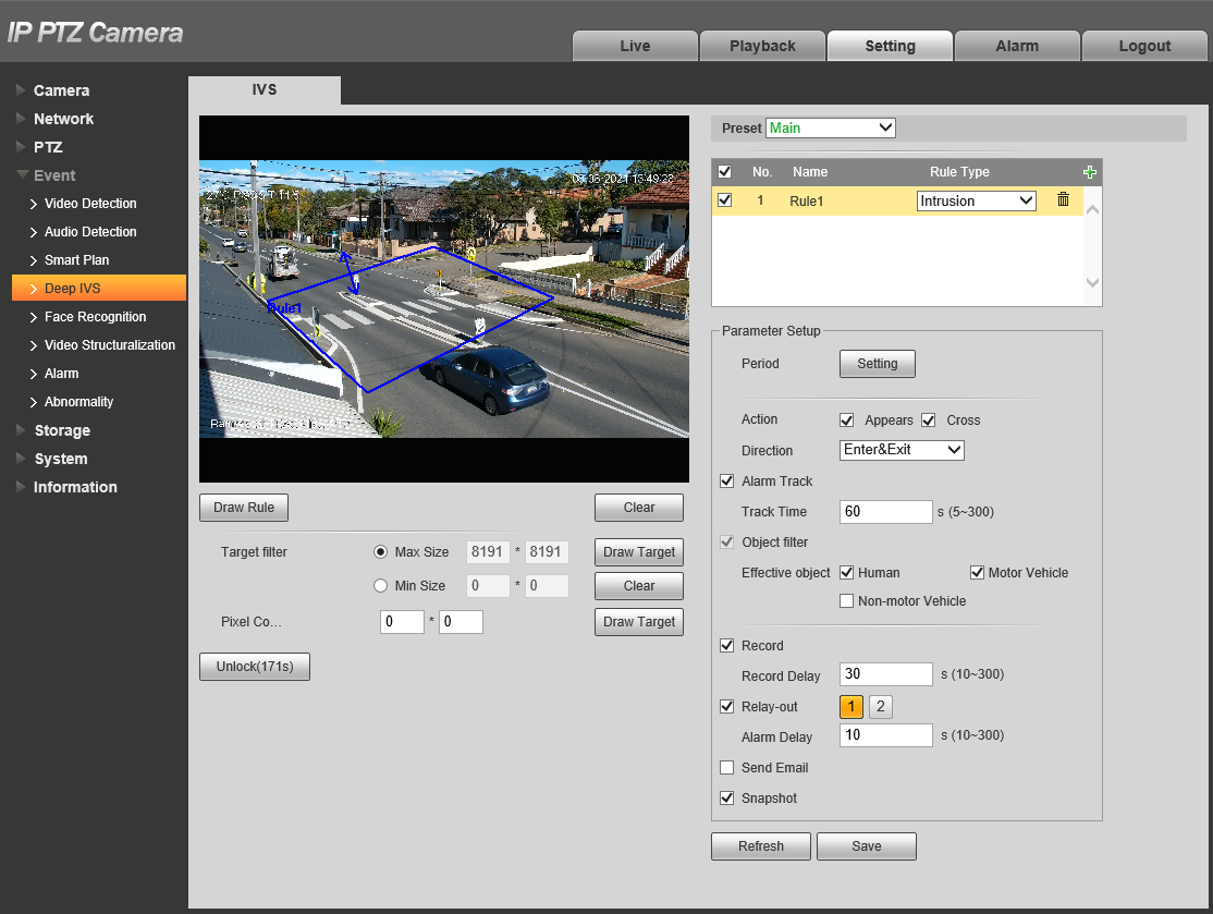
Intrusion (via Web Interface 3.0)
- Navigate to Setting > Event > Smart Plan

- Click Add Plan and select the Preset you wish to configure an intrusion on.
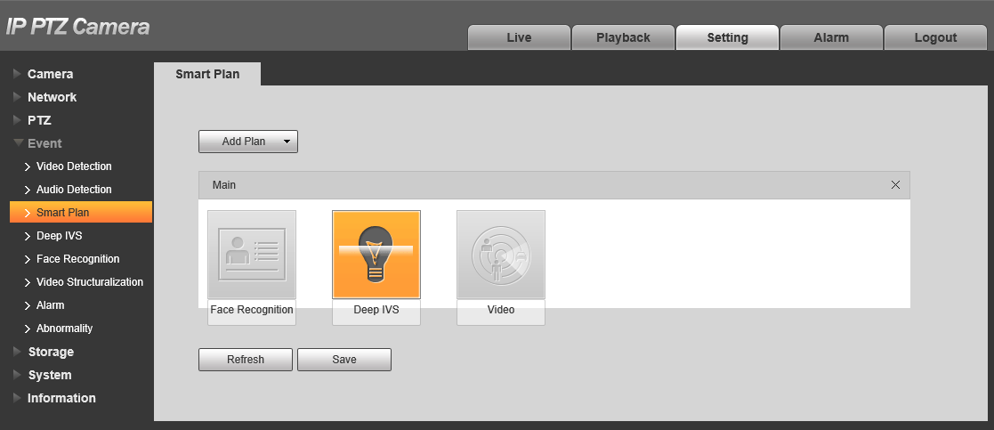
- Click Deep IVS.
- Click .

- Navigate to Setting > Event > Deep IVS
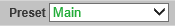
- Select the Preset you want to create the intrusion on.
- Click to add an IVS rule
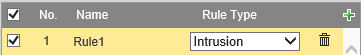
- Set the Rule Type to Intrusion.
- Click .
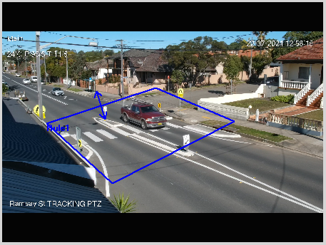
- Draw the Intrusion. Left-click on the camera feed to start drawing the Intrusion shape. Left-click to place additional corners. Right-click to finish placing the shape.
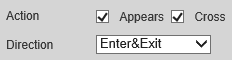
- Set the Action of the intrusion.
Appears will trigger if the target appears inside the intrusion. E.g. if the intrusion covers an area with a door.
Cross will trigger if the target crosses the intrusion line. - If Cross is selected, set the Direction of the Intrusion.
Enter&Exit will trigger when the target enters and exits the intrusion.
Enter will only trigger when the target enters the intrusion.
Exit will only trigger when the target exits the intrusion.
- Set the Effective object (AI Camera only) .
- Set the period by clicking .
- Repeat steps 1-8 for each additional Intrusion you wish to add.
- Click .
Additional Settings
| Parameter | Description |
| Max Size/Min Size | Set the size range of targets. Targets larger than the max size, or smaller than the min size will not trigger the intrusion. |
| Lock/Unlock | Locks/Unlocks the PTZs position while IVS is being configured. |
| Alarm Track | Enable to set the PTZ with track the target when the tripwire is tripped. |
| Track Time | Set how long the PTZ will track for. Requires Alarm Track to be enabled. |
| Record | Enable this option if you wish for the camera to record when The intrusion is triggered. This requires IVS to be scheduled on an NVR under Storage > Schedule > Record, and Auto to be selected for Record Mode under Storage > Record Control. |
| Record Delay | How long the camera will continue to record as part of the "IVS event" after the event has finished. |
| Relay-out | Enabling this will cause the relay of the camera to trigger when the intrusion is triggered. |
| Alarm Delay | How long the relay will stay triggered for after the intrusion is triggered. Requires Relay-out to be enabled. |
| Send Email | Send an Email when the intrusion is triggered. Requires configuration under Network > SMTP(Email) |
| Snapshot | A Snapshot will be taken when the intrusion is triggered is detected. IVS Snapshots will need to be set in the Schedule under Storage > Schedule > Snapshot |
Intrusion (via NVR)
-
Right-click on the Live view Page
- Select PTZ Control.
- Click the to open additional settings.
- Click the to open PTZ Config.
- Use the PTZ controls to move the PTZ to where you want to create the Preset.
- Click Setting to Save the Preset.
- Right-Click to Exit the PTZ Control Menu.
-
Right-Click and select Main Menu.
- Select AI.
- Select Parameters > Smart Plan
- Set the Channel to the PTZ's channel.
- Set the Preset to the preset created earlier.
- Click Add.
- Select the IVS Option for Smart Plan.
- Select Parameters > IVS.
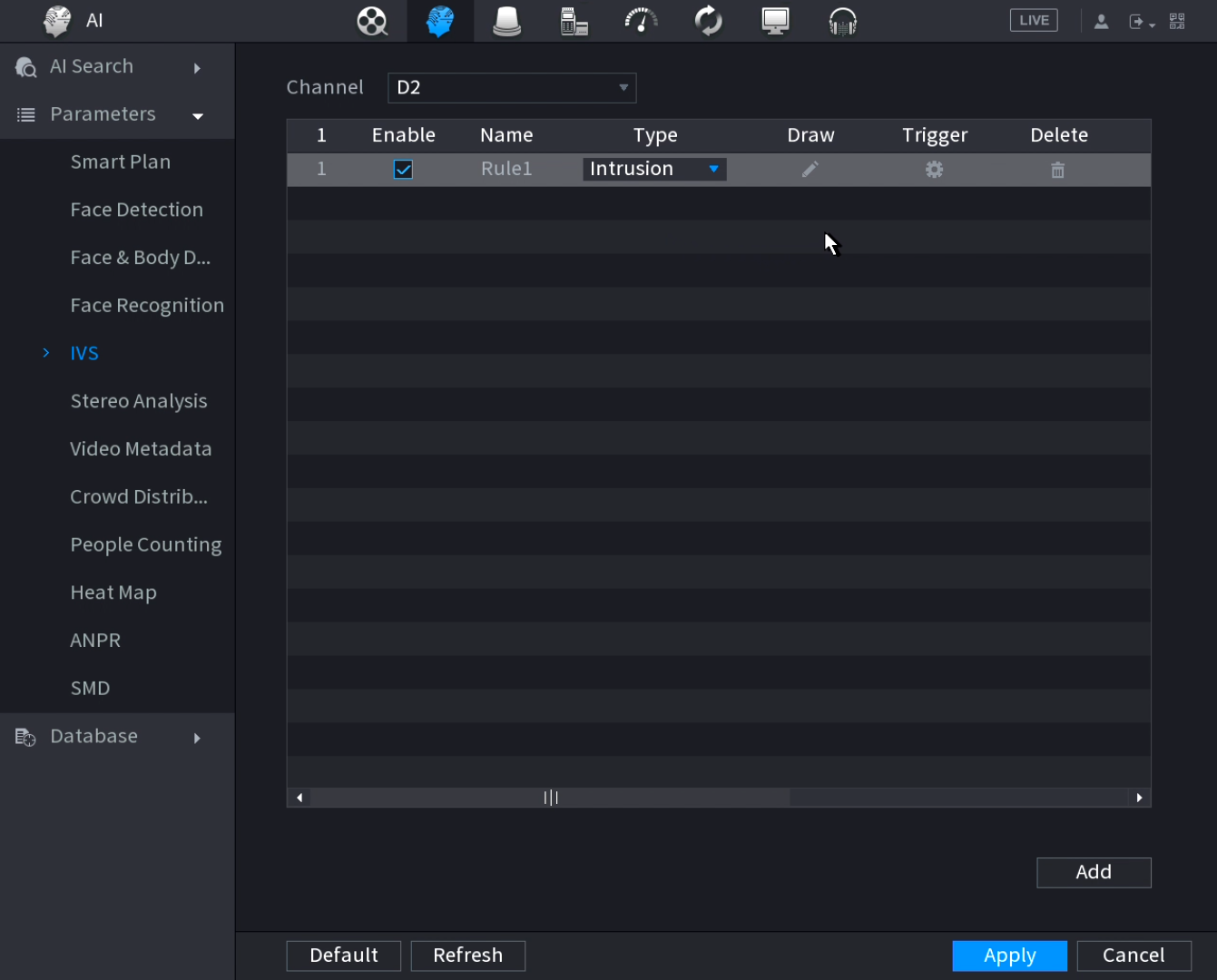
- Set the channel to the PTZ's channel.
- Click .
- Set the Type to Intrusion.
- Click the Draw icon.
- Set Preset to the Preset created earlier.
- Select the Draw Rule Icon.
- Left-click on the camera feed to start drawing the Intrusion shape. Left-click to place additional corners. Right-click to finish placing the shape.
- Set the Action of the intrusion.
Appears will trigger if the target appears inside the intrusion. E.g. if the intrusion covers an area with a door.
Cross will trigger if the target crosses the intrusion line. - If Cross is selected, set the Direction of the Intrusion.
Enter&Exit will trigger when the target enters and exits the intrusion.
Enter will only trigger when the target enters the intrusion.
Exit will only trigger when the target exits the intrusion. - (AI Cameras Only) Turn Target Filter On, and select Humans and/or Motor Vehicle. The Intrusion will only activate for the selected targets.
- (Optional) Set the Name of the Rule
- (Optional) Select Draw Target to configure the Min/Max size filters for the target.
- Click OK.
- Click Apply.
Additional settings
Click the Trigger Icon to configure additional settings.
| Parameter | Description |
| Schedule | Schedule the active ours of the IVS rule. This will only work from the NVR if AI by NVR is used. |
| Alarm Out | Sets an external alarm to activate whenever a face is detected. |
| Post-Alarm | Sets how long the system waits after a trigger before detecting again (10 seconds by default) |
| Alarm Track | Enable to set the PTZ with track the target when the tripwire is tripped. |
| Report Alarm | Updates the alarm system status on the network (Unused for this system). |
| Send Email | Notifies a specified email address whenever the event is triggered (Requires internet connection & setup) |
| Record | Enable this option if you wish for a camera to record when The intrusion is triggered. Sets which camera to record to when the event is triggered. This requires IVS to be scheduled on an NVR under Storage > Schedule > Record, and Auto to be selected for Record Mode under Storage > Record Control. |
| Post-Record | How long the camera will continue to record as part of the "IVS event" after the event has finished. |
| PTZ Linkage | Set PTZ behaviours in response to a event trigger, such as selecting a Tour to perform, etc |
| Tour | Set Tour behaviours in response to a event trigger. |
| Buzzer | Sets the NVR to beep whenever an event is triggered |
| Log | Log IVS details in the Log (enabled by default) |
| Alarm Tone | Plays a designated .wav file in response to an event trigger. This can be imported via a USB flash drive to the NVR. |
| Auto Tracking | Enable to allow auto tracking. |
| Tracking Duration | Set how long the PTZ will track for. Requires Alarm Track to be enabled. |
Abandoned Object & Missing Object
To configure Abandoned/Missing Object, follow the instructions for Intrusion but select Abandoned/Missing Object as the Rule Type.
Face Detection/Recognition
Face Recognition (via Web Interface 3.0)
- Navigate to Setting > Event > Smart Plan

- Click Add Plan and select the Preset you wish to configure the face recognition on.
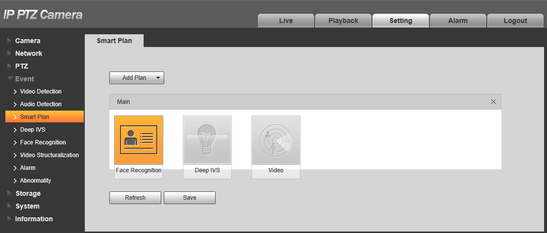
- Click Face Recognition.
- Click .
- Navigate to Setting > Event > Face Recognition > Face Detection
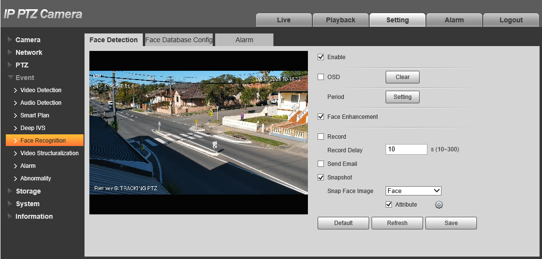
- Tick Enable to enable Face Detection.
- Tick Face Enhancement to enhance face captures.
- Enable Snapshot for the PTZ to save a snapshot when a face is detected.
- Set Snap Face Image to Face.
- Enable Attribute if you wish to detect specific face attributes, then click
 to set the face attributes (Age, Gender, Expression, Glasses, Mask, Moustache&Beard).
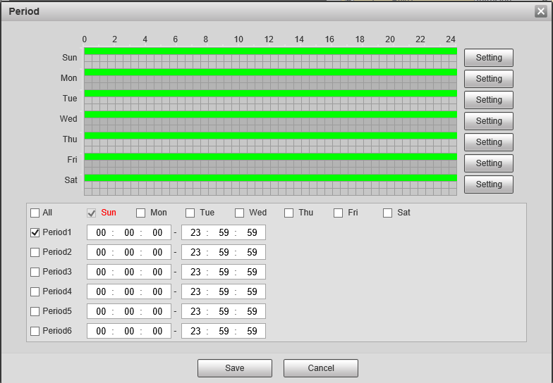
- Set the period by clicking .
- Click Save.
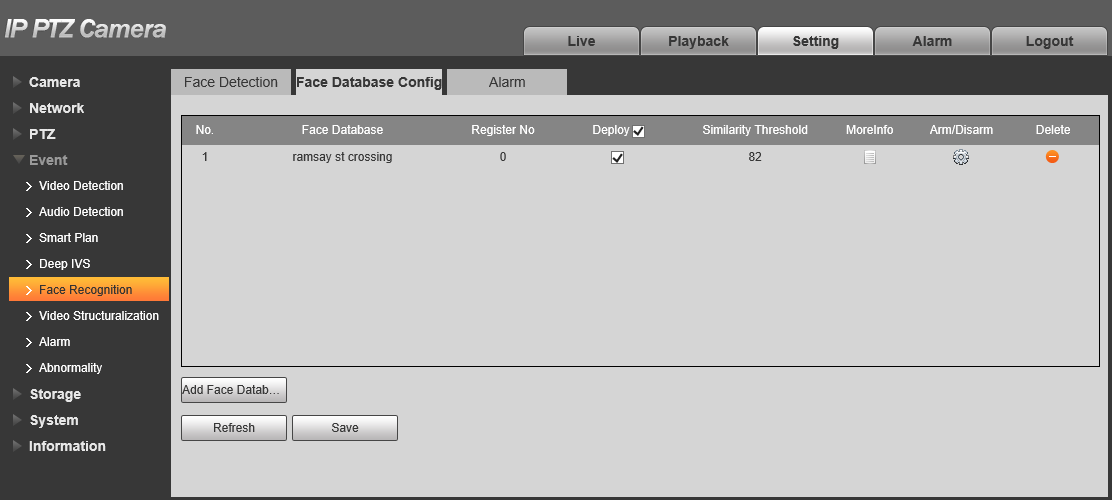
- Navigate to Setting > Event > Face Recognition > Face Database Config.
- Click Add Face Database.
- Tick Deploy.
- (Optional) Adjust the Similarity Threshold and/or the Arm/Disarm period.
- Click Save
Additional Settings
Adding Faces to the Face Database
- Navigate to Setting > Event > Face Recognition > Face Database Config.
- Click MoreInfo
 .
.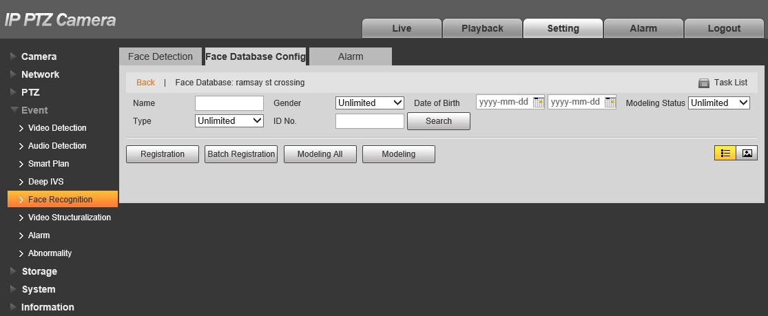
- Click Registration.
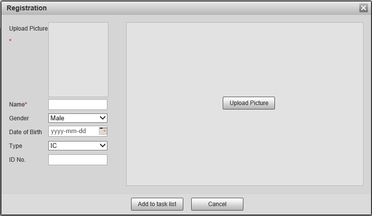
- Click Upload Picture, then select a picture from your computer.
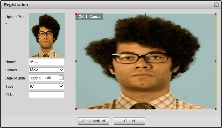
- Enter a Name and set the Gender. Then optionally add a Date of Birth, Type and ID No.
- Click Add to task list.
- Click Task list
 to view the list of current Add/Modify/Delete Tasks for the database.
- When the status says Operate Succeeded! the image has been successfully uploaded.
- Click Search to see the list of faces in the Database.
 will allow you to switch between image and detail mode.
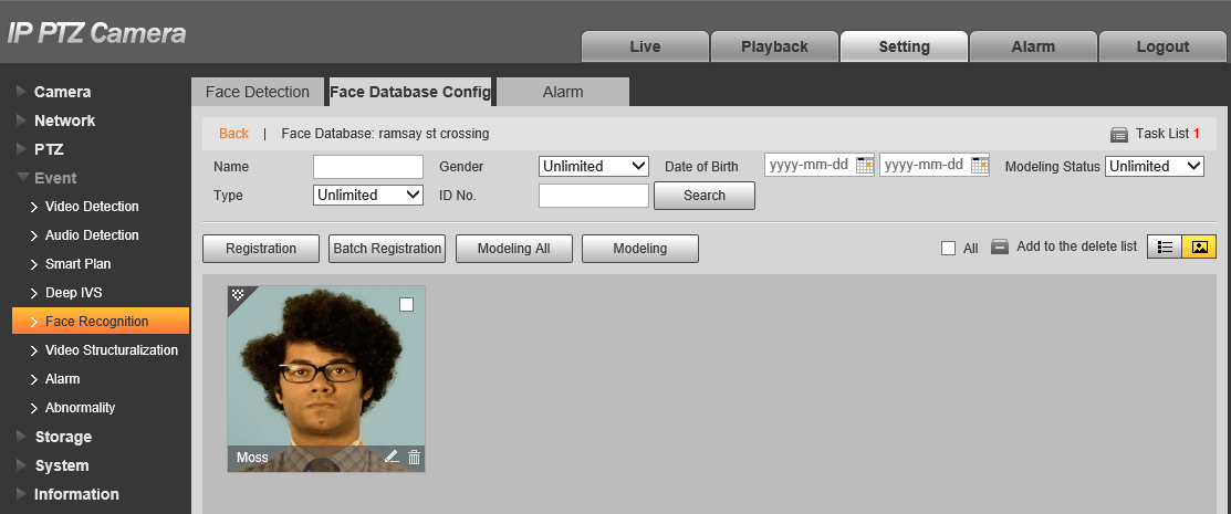
Alarm Out
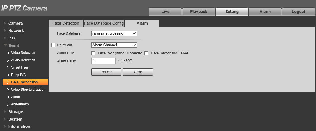
- Navigate to Setting > Event > Face Recognition > Alarms
- Select the Face Database.
- Enable Relay-Out and select the Alarm Channel.
- Enable Face Recognition Succeeded and/our Face Recognition Failed to trigger the Alarm Output when a Face is and/or isn't recognised.
- Set the Alarm Delay. This is how long the alarm will trigger for.
Auto Tracking
After an IVS rule (Intrusion is recommended) is configured you can enable Auto Tracking for that rule.
Auto Tracking (via Web Interface 5.0)
- Navigate to AI > Smart Plan.
- Select
 and then
  .
. - Enable Auto Tracking
 .
. - Set the Tracking Duration (60s or less is recommended)
- Select
 .
.
Auto Tracking (via Web Interface 3.0)
- Navigate to Setting > Event > Deep IVS
- Select the Rule you wish to add the Auto Tracking to.
- Enable Alarm Track.
- Set the Track Time (60s or less is recommended)
- Click Save.
Auto Tracking (via BlackUI NVR)
-
Right-Click and select Main Menu.
- Select AI.
- Select Parameters > IVS.

- Set the channel to the PTZ's channel.
- Click the Trigger Icon
 for the rule you want to add Auto Tracking to.
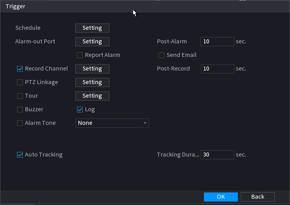
- Enable Auto Tracking.
- Set the Tracking Duration. Recommended Tracking Duration is 60 sec or lower.
- Click OK.
- Click Apply.
Additional Configuration
Wiper
In the Web Interface's live view click  to control the wiper. Once will cause it to wipe once. Start/Stop will cause it to Start/Stop wiping.
You can also configure the wiper to turn on automatically when it is raining, or set it to manual mode and configure how long the a single wipe will last/how long the wiper will be active.
Wiper Configuration (via Web Interface 3.0)
To configure the Wiper navigate to Setting > System > Peripheral > Wiper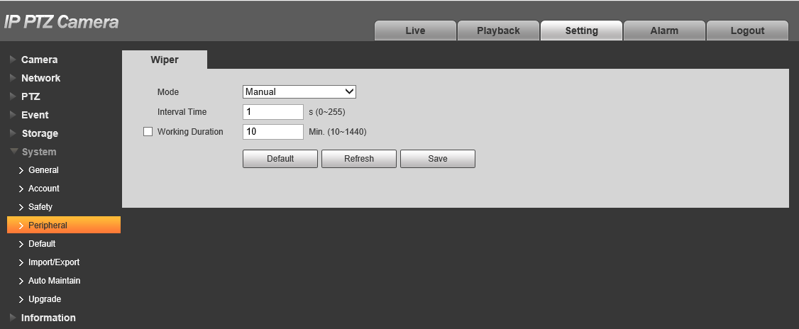
| Parameter | Description |
| Mode | Choose between Manual & Auto. Manual is the default option. It will allow you to configure the Interval Time and Working Duration. In Manual mode you will have to manually start the wiper. |
| Interval Time | The time between the wiper starting & ending, i.e. how long it takes for the wiper to wipe forward & back. |
| Working Duration | Set how long the Wiper will operate for once it has been started. The value ranges from 10 to 1440 minutes |
Install Mode (For Positioning PTZ)
When installing a Positioning PTZ camera, you will need to set the Install Mode to indicate which way the camera is installed. This will flip the image and correct the Pan/Tilt direction so it matches the install direction.
Install Mode Configuration
When installing a Positioning PTZ camera, you will need to set the Install Mode to indicate which way the camera is installed. This will flip the image and correct the Pan/Tilt direction so it matches the install direction.
The setting must be changed in the Web interface of the PTZ under Setup > System > General > General.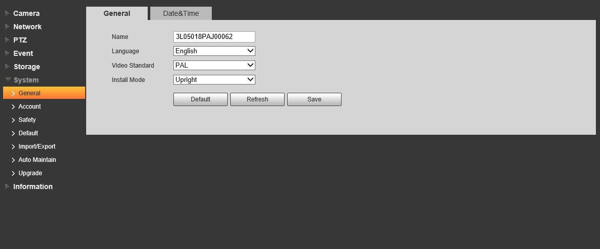
EIS (Electronic image stabilization)
EIS is used to reduce image shaking during use to allow for clearer images. It is Off by default. EIS can only be configured in the Web Interface.
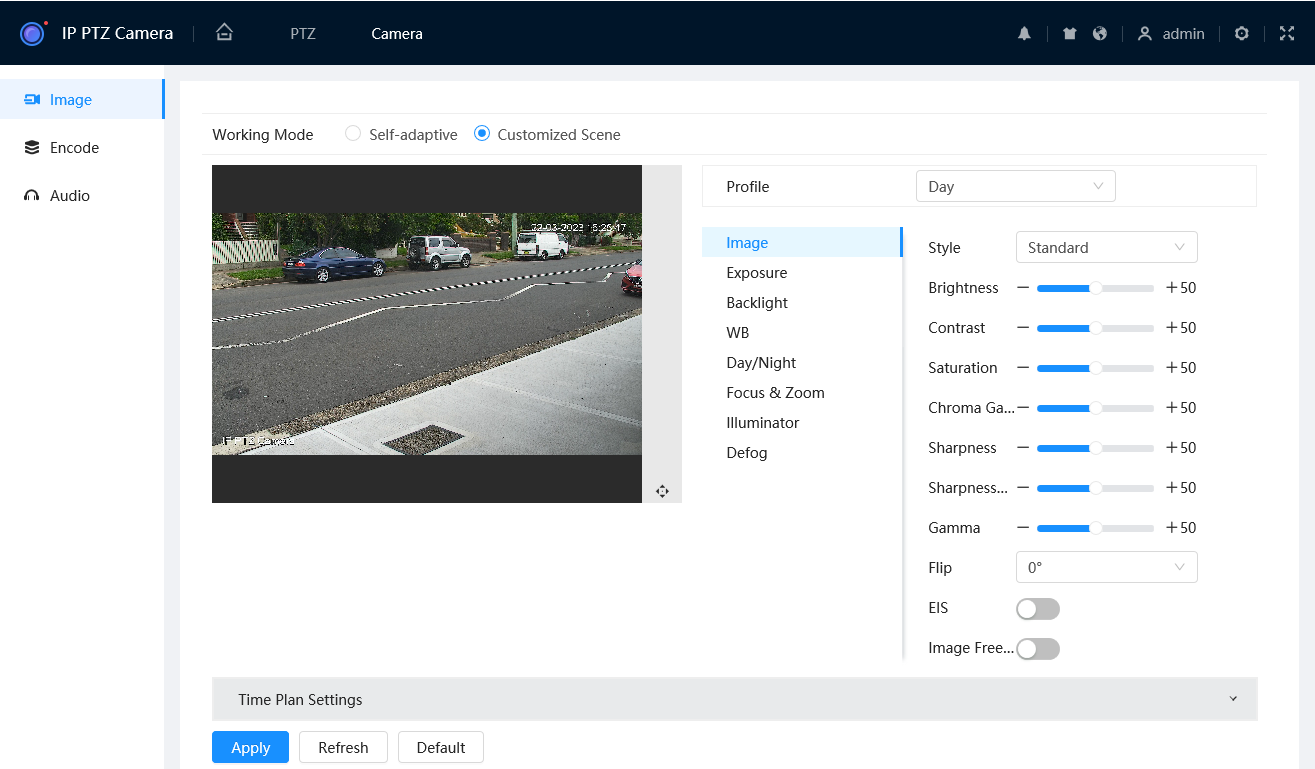
EIS Configuration (via Web Interface 5.0)
To configure EIS navigate to Setting  > Camera > Image > Image
Set EIS to On/Off
EIS Configuration (via Web Interface 3.0)
To configure EIS navigate to Setting > Camera > Conditions > Conditions > Picture
Set EIS to On/Off 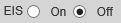
PTZ Limit
PTZ Limit can be used to set how far up/down the PTZ can move. It can only be configured in the Web Interface.
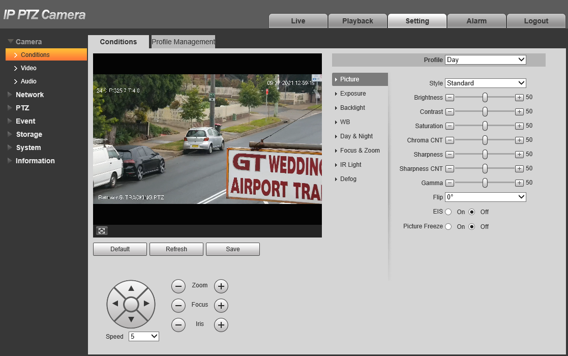
PTZ Limit Configuration (Via Web Interface 5.0)
Navigate to Setting  > PTZ > PTZ Rotation
- Use the PTZ controls to move the PTZ as high as you wish it to go, then press
 to set the Up Limit.
 - Use the PTZ controls to move the PTZ as low as you wish it to go, then press
 to set the Down Limit.
 - Click
 to preview the already-set Up Line and Down Line.
 - Toggle Enable to ON
 to enable the PTZ Limit function.
PTZ Limit Configuration (Via Web Interface 3.0)
To configure PTZ Limit navigate to Setting > PTZ > Function > PTZ Limit
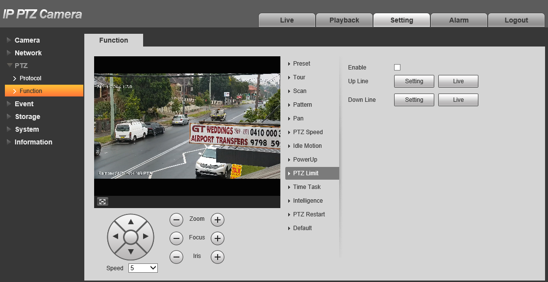
- Use the PTZ controls to move the PTZ as high as you wish it to go, then press
 to set the Up Line.
 - Use the PTZ controls to move the PTZ as low as you wish it to go, then press to set the Down Line.
- Click
 to preview the already-set Up Line and Down Line.
- Tick Enable to enable the PTZ Limit function.
Date & Time
Set the Date & Time, DST (Daylight Savings) and NTP (Network Time Protocol. Time & Date synchronisation with a server) for the PTZ.
The Date & Time will be pushed from the NVR if the PTZ is connected to one.
Date & Time Configuration (Web Interface 5.0)
To configure the date & time navigate to Setting  > System > General > Date & Time
Date & Time
- Set the Date Format. Choose between DD-MM-YYYY, MM-DD-YYYY and YYYY-MM-DD.
- Set the Time Format. Chose between 24-Hour and 12-Hour format.
- Set the Time Zone. Choose your Time Zone.
- Set the Current Time. Click to use the current time & date
DST (Daylight Savings)
In Australia DST is used in New South Wales, Victoria, South Australia, Tasmania, the Australian Capital Territory and Norfolk Island only.
- Enable DST
 .
. - Set DST Type, Start Time and End Time. Correct settings for Australia are in the image above.
NTP (Network Time Protocol)
NTP is used to sync the Time & Date of the PTZ to the time and date of a server. This feature requires internet access.
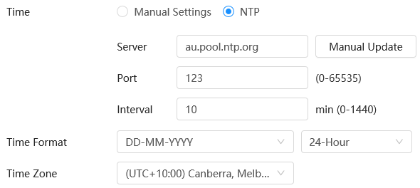
- Set Time to NTP
- Set the Time Zone to ensure the correct date & time is pulled from the server.
- Set Server, Port & Interval. Recommended settings for Australia are in the image above.
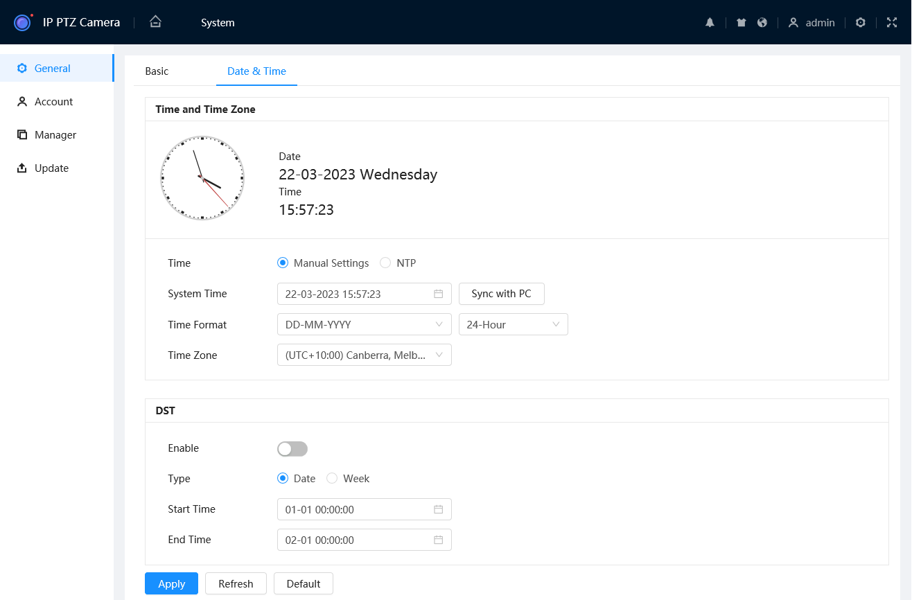
Date & Time Configuration (Web Interface 3.0)
To configure the date & time navigate to Setting > System > General > Date& Time
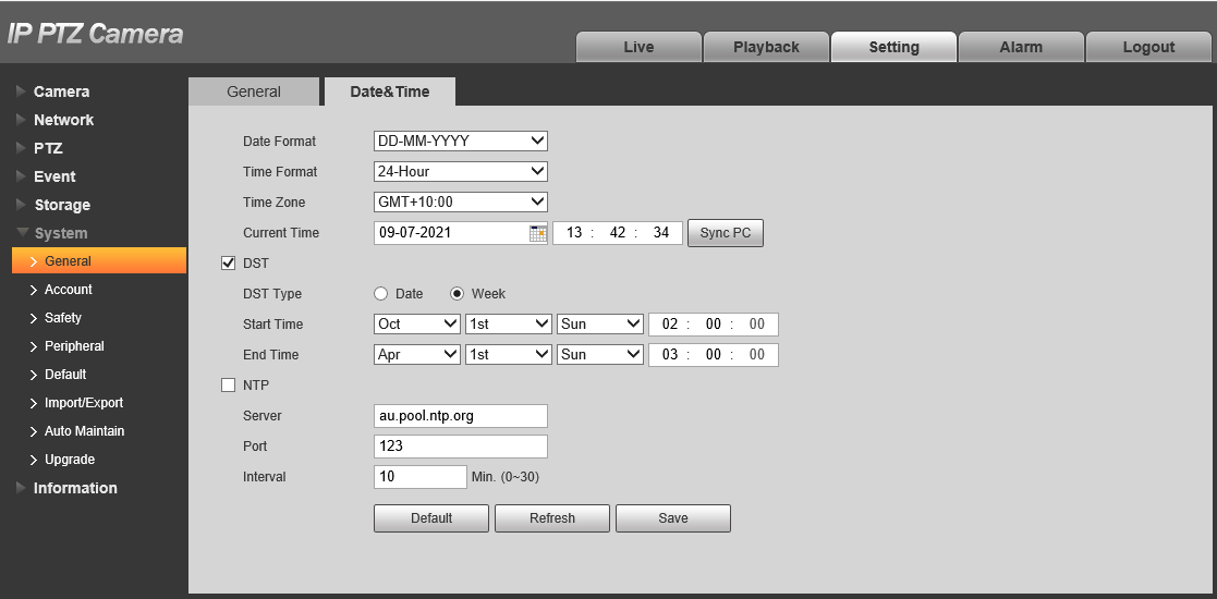
Date & Time
- Set the Date Format. Choose between DD-MM-YYYY, MM-DD-YYYY and YYYY-MM-DD.
- Set the Time Format. Chose between 24-Hour and 12-Hour format.
- Set the Time Zone. Choose your Time Zone.
- Set the Current Time. Click to use the current time & date
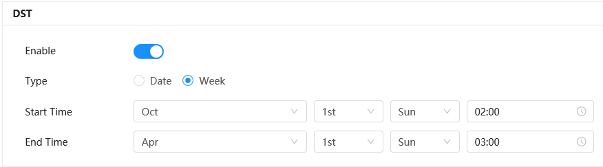
DST (Daylight Savings)
In Australia DST is used in New South Wales, Victoria, South Australia, Tasmania, the Australian Capital Territory and Norfolk Island only.
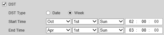
- Enable DST.
- Set DST Type, Start Time and End Time. Correct settings for Australia are in the image above.
NTP (Network Time Protocol)
NTP is used to sync the Time & Date of the PTZ to the time and date of a server. This feature requires internet access.
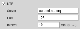
- Enable NTP
- Set the Time Zone to ensure the correct date & time is pulled from the server.
- Set Server, Port & Interval. Recommended settings for Australia are in the image above.
Auto Maintain - Auto Reboot
Auto Reboot can be configured to set the PTZ to reboot at a set Day and Time.
Auto Reboot Configuration (via Web Interface 5.0)
To configure the Auto Reboot navigate to Setting  > System > Manager > Maintenance
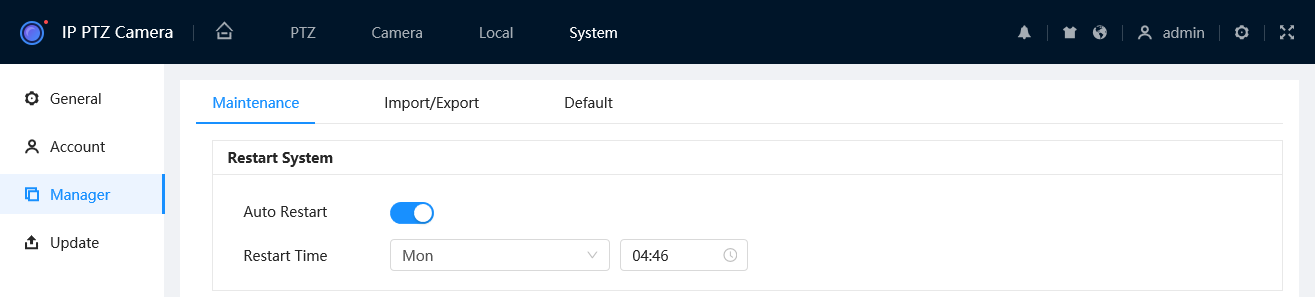
- Toggle Auto Restart to On

- Set the Restart Time
- Select
 to save your changes.
Auto Reboot Configuration (via Web Interface 3.0)
To configure the Auto Reboot navigate to Setting > System > Auto Maintain > Auto Reboot
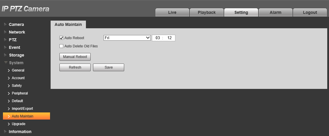
- Tick Auto Reboot
- Select the Day of the Week. Everyday, Sun, Mon, Tue, Wed, Thu, Fri, Sat.
- Set the Time.