How to charge the VSTEST
- Connect an Ethernet cable hooked up to a POE source to the VSTEST's PD / CHARGE port to charge

- Check the front of the VSTEST to see if the charge indicator light is on.

How to test an IP Camera
- Power on the VSTEST

- Connect the camera or network switch (or PoE) or router to the blue PSE port via Ethernet cable for POE

- Select ONVIF Test and press the right arrow button

- You will now see the Link test screen, the purpose of this screen is to show you the Link metrics that the VSTEST can read. This screen indicates (from right to left):
- The speed you are connected at (10/100/1000 mbps)
- The amount of data in and out of the IP Camera
- The health of the connection (represents signal over distance of cable)
- The (Blue) PSE which is the PoE output port or (below is Green) PD which is the PoE input (both are for data)
- At the end is a Voltage and Wattage indicator.
Below this area is: - The system IP, which acts as a host to the device(s) connected
Below this is the button map: - Pressing the ZOOM + and ZOOM - button will Set link Speed up or down (10/100/1000 mbps)
- Pressing the SET button will manually let you configure your host IP for the VSTEST
- Pressing the Focus - button will set DHCP automatically fetching an IP (Hosting IP, requesting device domain [i.e. ip camera] with VSTEST)
- Pressing the IRIS - button will Search DHCP to automatically fetch an IP (Connecting to a hosting IP with VSTEST)
- Pressing the -> (right arrow) button will send you to the Discover tab
- You should now be in the discover tab which finds IP's and connects to them. There should be a list of IP's if connected to a switch or router simultaneously, if only connected to a single camera only one IP should show up. Use the arrow keys to highlight the network device and it should load a screen shot if connected correctly to the IP Camera.
Below this is the button map:- Pressing the SET button will manually let you configure the IP Camera's IP
- Pressing the ZOOM + and ZOOM - button will Set link Speed up or down (10/100/1000 mbps)
- Pressing the Focus - button will refresh the IP's
- Pressing the IRIS - button will refresh the picture
- Pressing the -> (right arrow) button will send you to the Video & PTZ tab

- Press the right arrow to go to the next page
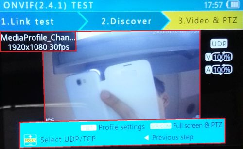
- The Video & PTZ tab should now populate the cameras stream. In the left hand corner it should display the resolution and FPS from the stream. From this tab you can select UDP or TCP, and also change the camera's stream settings.
How to test a CVI Camera
- Connect the camera's power with the DC 12v OUTPUT on the VSTEST or use a Power adapter for Cameras over 12 volts / 2amps input

- Use a HDCVI or Analog cable to connect the camera's HDCVI or Analog port to the VSTEST's VIDEO IN port
- Now select Analog camera test and press the right arrow button

- You should now see a live video feed from the camera or output video device you are connected to. Press the SET button to configure PTZ control, Press the SCR button to go full screen.

How to record/playback footage
Once you have a video input under the ONVIF Test or Analog Camera test do the following.
- Press the SCR button to go to full screen mode. There we will find the option to record the video input

- Now open the button panel to reveal the QWERTY keyboard

- Pressing Z will record the stream/channel, and pressing it again will stop the recording

- After pressing Z for the second time a prompt will tell you Video record Finished. YEAR-MONTH-DAY_HOUR-MIN-SEC.avi

- Press MODE to got back to the main screen, and use the arrow buttons to select Record Playback and push the right arrow key to access saved video on the VSTEST

- This page will display a file explorer where your video will be saved to. Navigate to your folder using the arrow keys and use the right arrow button.

- Now select the clip you want to play with the arrow keys. Press the SCR button to go full screen for more playback options

How to test POE
- Connect the Ethernet cable from the POE network switch or Midspan POE Injector or POE router to the Green PD port


- Now select "ONVIF Test" and press the right arrow button

- You will now see the Link test screen, the purpose of this screen is to show you the Link metrics that the PFM900 can read. This screen indicates (from right to left):
- The speed you are connected at (10/100/1000 mbps)
- The amount of data in and out of the IP Camera
- The health of the connection (represents signal over distance of cable)
- The (Blue) PSE which is the PoE output port or (below is Green) PD which is the PoE input (both are for data)
- At the end is a Voltage and Wattage indicator.

How to test RJ45 and determine length
- Plug your ethernet cable into one of the ports and select RJ45 TDR TEST at the home screen and press the right arrow key

- Make sure the other end of your Ethernet cord is left unplugged, now press the + Zoom button to test the length of the cable on port 1. This test uses TDR (Time Domain Reflection) analysis to determine the state of the cable. After the tape measure flashes on the screen the approximate length of the cable will populate on the middle of the screen.

- To test the Ethernet cable for continuity (connected, open, and short) you will need to plug in each end of the cable to the VSTEST and press the + ZOOM button, and after the first test then the - ZOOM button. You can also press the SET button to repeatedly do this test however your results will vary, and the cable length read might not be entirely accurate. The picture below shows that 4 cables are connected and in the red boxes 4 cables are open:

- Also if you see this symbol on your screen during this test, then the > symbol means there is a short between the two wires on the screen.

- Conducting a continuity test on a working cable should give you the — symbol meaning that the cables are properly connected.

How to test Audio
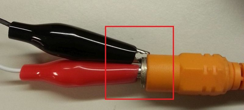
- Get all of the required cables into one place and install the 3.5mm cord into the audio in jack on the VSTEST and attach the alligator clip (pink box in the diagram below) to the audio output's ground connector, and attach the second alligator clip (red box in the diagram below) to the signal contact.


- Now outside of the back of the VSTEST you should hear the audio output while the VSTEST is ON

How to scan Networks
- Connect the Ethernet cable to the VSTEST and select Network tools with the arrow buttons, enter the menu with the right arrow button

- Now press the SET button to setup your connection to the network

- For easy setup let the device Use DHCP, otherwise select static IP and configure your VSTEST's IP Address, Mask, gateway, DNS settings, and then press the + IRIS button to confirm settings or the SET button to exit out.

- Now press the + FOCUS button to perform a network ping test, this test will locate all public IP addresses on your immediate network via your devices settings. Press the + FOCUS button when finished.

- To list the subnet IP's and the latency (ping in milliseconds) to them press - FOCUS and the VSTEST will do an active search on your network. once finished press - FOCUS again.

- To ping an external website (such as www.google.com) from the VSTEST on your network please open your keyboard and type out the url

- After typing in the URL close the keyboard and press the + ZOOM key to ping the website. This screen should show you how long it takes for the device to connect to the specified website.

How to change a HDCVI camera to Analog
- Connect the camera's power with the DC 12v OUTPUT on the VSTEST or use a Power adapter for Cameras over 12 volts / 2amps input

- Use a HDCVI or Analog cable to connect the camera's HDCVI or Analog port to the VSTEST's VIDEO IN port

- Now select ONVIF Test and press the right arrow button

- You should now see a live video feed from the camera or output video device you are connected to. Press the SET button to configure PTZ control, Press the SCR button to go full screen

How to Reset an IP camera.
- Connect the camera or network switch (or PoE) or router to the blue PSE port via Ethernet cable for POE.

- Now select ONVIF Test and press the right arrow button

- You should see a link similar to the picture below if setup correctly Once finished with setting the VSTEST's IP address please press the right arrow button for next.

- You should now be in the discover tab which finds IP's and connects to them. There should be a list of IP's if connected to a switch or router simultaneously, if only connected to a single camera only one IP should show up.
Use the arrow keys to highlight the network device and then press on SET button.
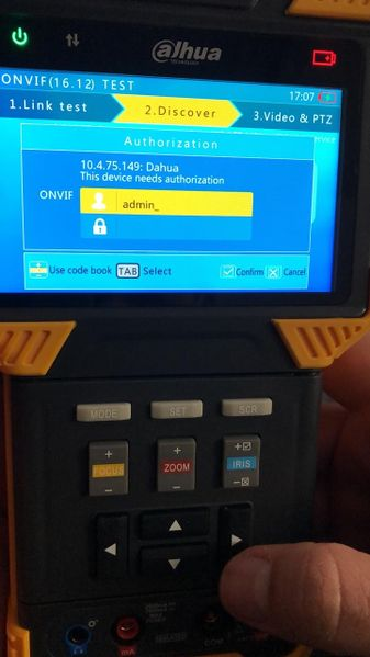
- You will now see the login screen to enter IP Camera credential. Enter the correct login credential for your IP Camera and press IRIS+ button. Use TAB button to switch from Username to Password text-field.


- Once you are on the Camera Settings menu, use arrow button to go down to System. And then press on > button once to enter System menu.
- Press the down arrow button once, to go to Factory Default option. Selected option is the one with Yellow Line. Press IRIS+ button for save and execute the default.

- Press on IRIS+ button again to confirm to reboot after default.
- Your device will now go back to factory default setting with default IP Address.
