ACLOC100
Fail Secure Strike
Fail-Secure= If there is a power failure the lock will not open. This also means power needs to be applied for the lock to open.
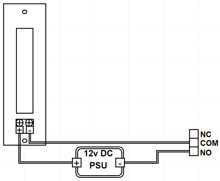
In the image below, the strike is wired into a Normally Open Relay Contact. This will stop power from being sent to the device and will stay locked UNTIL the relay is triggered.
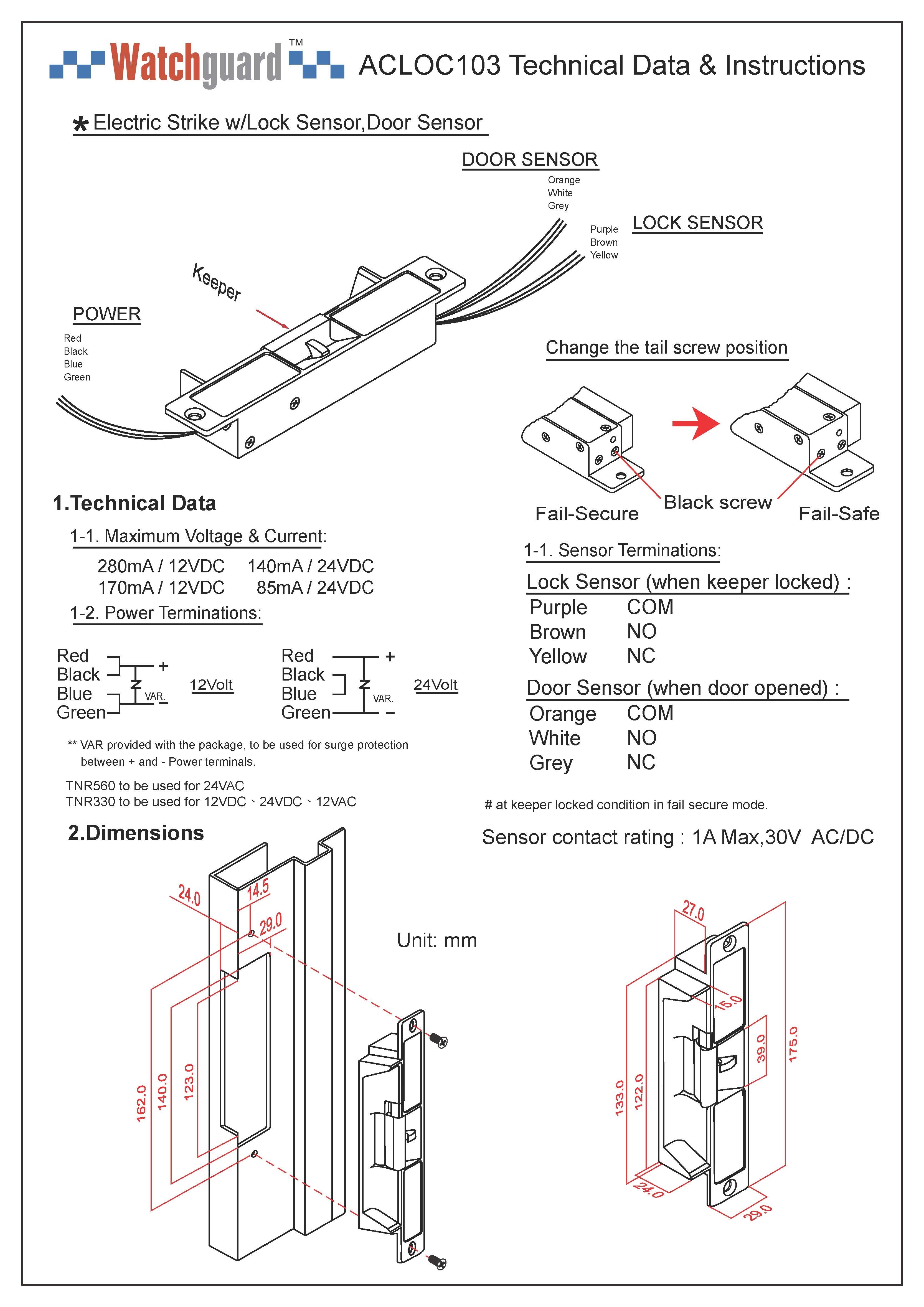
ACLOC103
Panel content
Fail Secure Connnection - Latch open during power failure
Fail Safe Connnection - Latch closed during power failure
Wiring of the electric strike is the same, just change NO (Normally Opened) to NC (Normally Closed) in the above procedures.
If 12V is used to supply the electric strike:
1) Connect Red and Black wires together and connect these 2 wires to the positive terminal of a +12V supply, i.e. +12V.
2) Connect Blue and Green wires together and connect these 2 wires to the NO (Normally Opened) terminal of the access controller door lock output relay.
3) Connect the COM (Common) terminal of the access controller door lock output relay to the negative terminal of the power supply, i.e. 0V/GND.
If 24V is used to supply the electric strike:
1) Connect Red wire to the positive terminal of a +24V supply, i.e. +24V.
2) Connect Green wire to the NO (Normally Opened) terminal of the access controller door lock output relay.
3) Connect Black and Blue wires together.
3) Connect the COM (Common) terminal of the access controller door lock output relay to the negative terminal of the power supply, i.e. 0V/GND.
Door Sensor Connection
If door timeout or intrusion warning notification is required. You must connect the door sensor to the access controller.
1) Connect the White wire to SR terminal of the Door Sensor input terminal block.
2) Connect the Orange wire to GND terminal of the Door Sensor input terminal block.
Remember to configure the Smart PSS to active the Door timeout function. Please see the section: Intelligent function - Setting up the door open timeout
\